Modular agricultural toolbar

a toolbar and module technology, applied in the field of agricultural toolbars, can solve the problems of insufficient soil for crop cultivation, large amount of preparation time for cultivating crops, and large amount of time spent preparing to cultivate crops rather than actually cultivating, so as to reduce soil compaction frequency, facilitate propulsion, and reduce soil compaction

a toolbar and module technology, applied in the field of agricultural toolbars, can solve the problems of insufficient soil for crop cultivation, large amount of preparation time for cultivating crops, and large amount of time spent preparing to cultivate crops rather than actually cultivating, so as to reduce soil compaction frequency, facilitate propulsion, and reduce soil compaction

US20190313568A1Pending Publication Date: 2019-10-17ANDERSON DENNIS

Image

  • Modular agricultural toolbar
  • Modular agricultural toolbar
  • Modular agricultural toolbar

Examples


Embodiment Construction

[0032]The present invention is described in reference to the accompanying drawings and following embodiments that are presented for the purpose of illustration and should not be construed to limit the scope of the invention thereto.

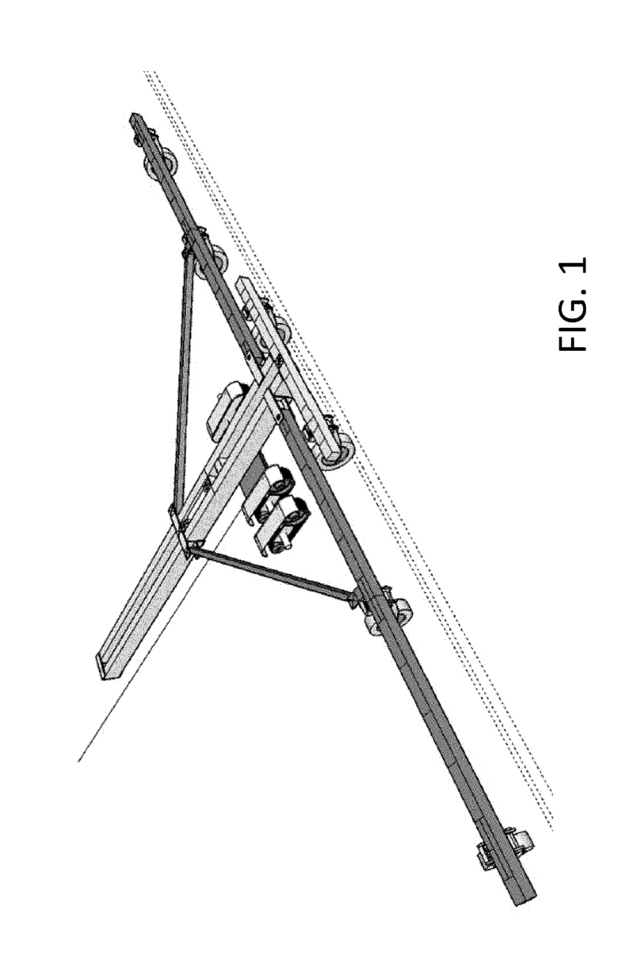
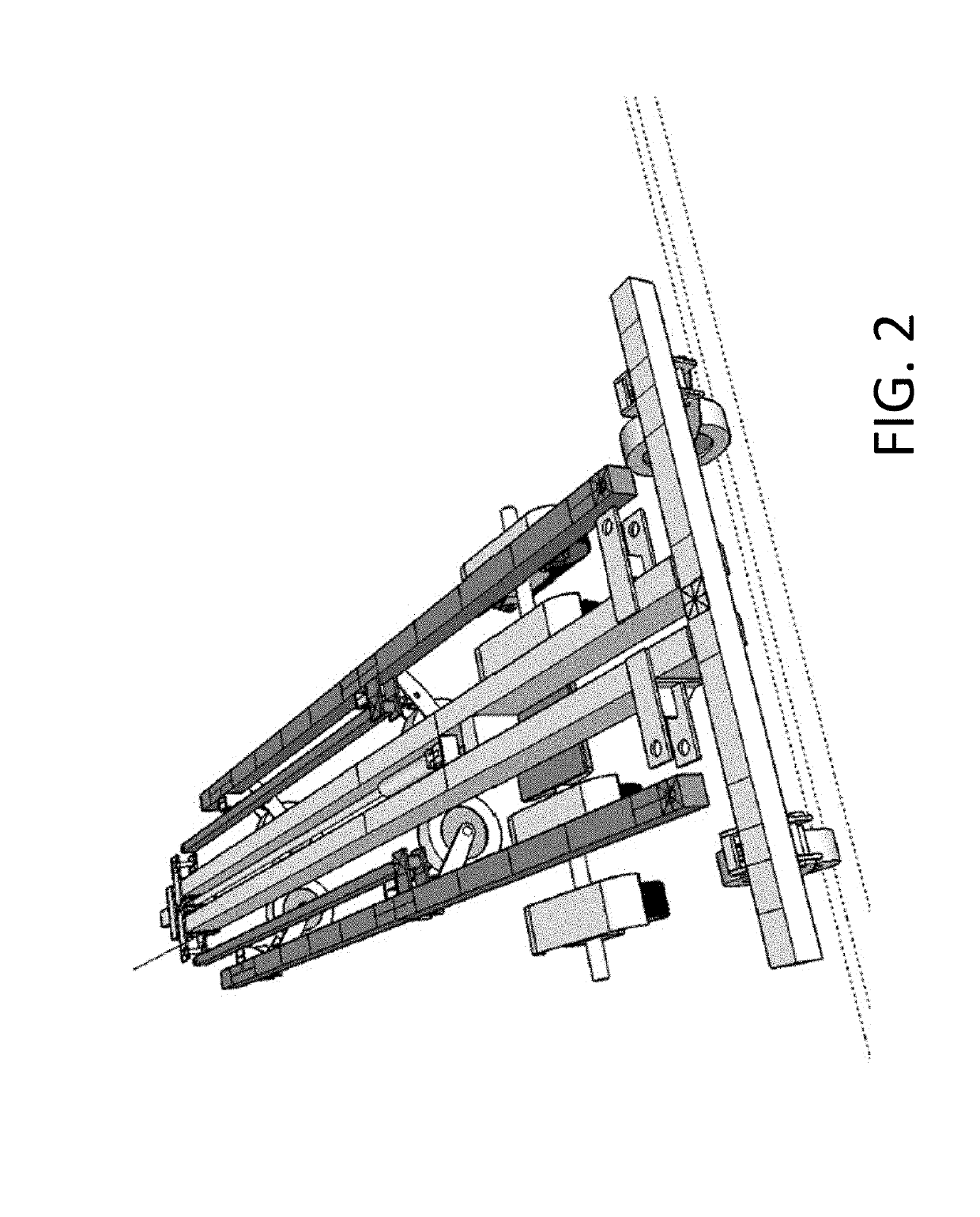
[0033]FIG. 1 illustrates a perspective view of the modular agricultural toolbar in an operational configuration while FIG. 2 illustrates a perspective view of the modular agricultural toolbar in a storage configuration. The embodiment of FIGS. 1 and 2 comprises a core frame, a plurality of pivotal support members, and at least one implement attachment member. A plurality of rail members coupled at a first end by an end plate and at a second end by an abutting member forms the core frame of the agricultural toolbar. The core frame of the modular agricultural toolbar further comprises a sled bracket movably coupled to the plurality of rail members, configured to couple an end of at least one support member and to move along the length of the core frame. In ...


PUM


Abstract

A modular agricultural toolbar comprising at least one retractable implement attachment member capable of accommodating various agricultural implementations, as well as a plurality of continuous track units for operational use and a plurality of wheels for transportation and storage use. The implement attachment members further capable of extending along a central axis, increasing the coverage areas of a given agricultural process while also being capable of folding horizontally alongside the core frame of the toolbar to enable ease of transportation and storage.

Description

CROSS-REFERENCE TO RELATED APPLICATIONS[0001]This invention claims priority from the previously filed provisional application, U.S. Pat No. 62 / 658,710, filed Apr. 17, 2018; the contents of which are herein incorporated by reference.BACKGROUND OF THE INVENTION[0002]The present invention relates to agricultural toolbars. Specifically, a modular agricultural toolbar that can accept various agricultural implements, hydraulically adapt implement elevation in reaction to variable terrain, and hydraulically compact on itself for ease of transportation and storage.[0003]The modern agricultural industry utilizes various processes in cultivating crops over large tracts of land, spanning upwards of a square mile in area. Over the course of the period from planting to harvesting a crop, this area of farmland may undergo a multitude of machine-assisted processes such as sowing, fertilization, pesticide and herbicide treatment, irrigation, and harvesting. In most instances, each process is perfor...

Claims


Application Information

Patent Timeline
17 Oct 2019
Publication
US20190313568A1
IPC
A01B73/06; A01B49/06; A01C7/00
CPC
A01B49/06; A01B73/065; A01C7/06; A01C7/00; A01C23/047; A01C7/208
Inventors
ANDERSON, DENNIS