Manual focus device and autofocus camera

a focus device and focus technology, applied in the direction of camera focusing arrangement, exposure control, printers, etc., can solve the problems of high manufacturing cost of phase difference detection method and high manufacturing cost of construction, and achieve the effect of easy focusing

Inactive Publication Date: 2005-09-01
FUJIFILM CORP +1
View PDF5 Cites 53 Cited by
  • Summary
  • Abstract
  • Description
  • Claims
  • Application Information

AI Technical Summary

Benefits of technology

[0010] In view of the foregoing problems, an object of the present invention is to provide a manual focus device and autofocus camera in which an in-focus state can be indicated and focusing can be easily effected.

Problems solved by technology

However, there occurs a high rise in the manufacturing cost for the construction to calculate the defocus amount according to the triangulation method.
Similarly, the phase difference detection method requires a high manufacturing cost, because of an optical system for splitting and introducing object light, a line sensor, and other relevant elements.

Method used


Image

  • Manual focus device and autofocus camera
  • Manual focus device and autofocus camera
  • Manual focus device and autofocus camera

Examples


Embodiment Construction

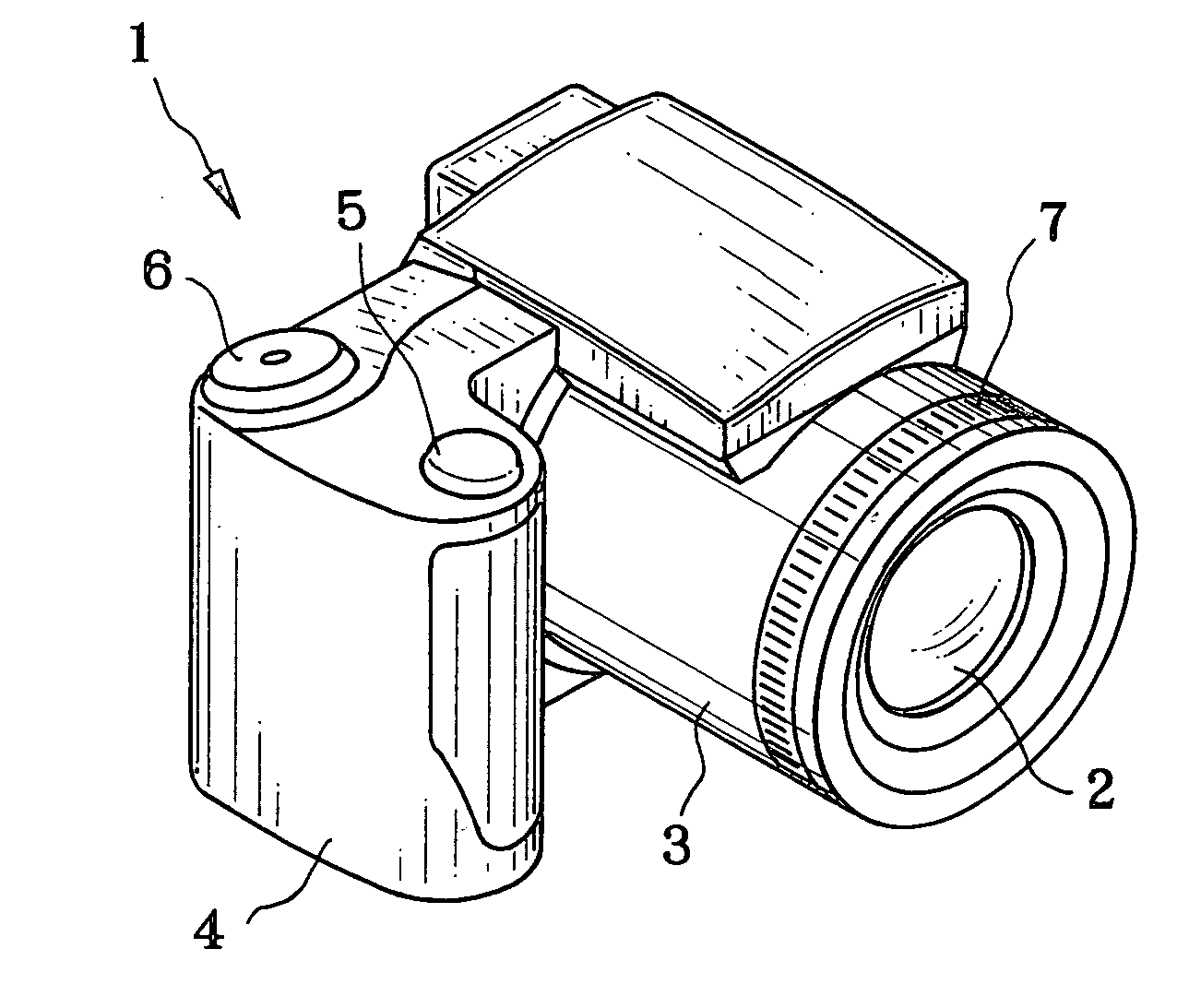
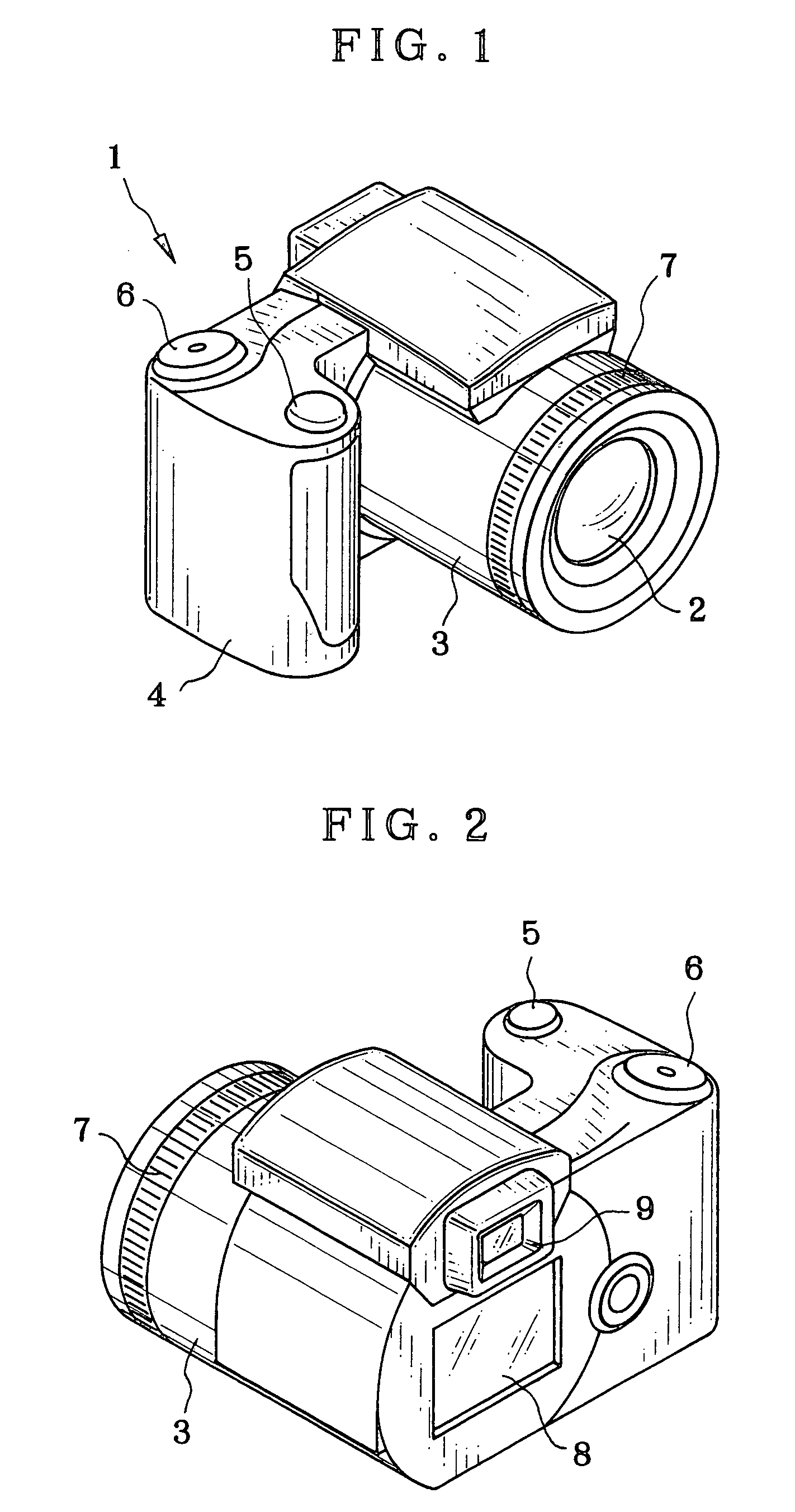
[0055] In FIG. 1, a digital still camera 1 of the invention is constituted by a lens barrel 3, a grip 4, a release button 5 and a mode selection dial 6 as mode switch. A taking lens system 2 is mounted in the lens barrel 3. The release button 5 has a construction depressible in a halfway step and a fully depressed step. A focusing ring 7 of a focusing lens driving mechanism is disposed around the lens barrel 3, and rotatable for focusing the taking lens system 2 to a photographic object.

[0056] In FIG. 2, the rear of the digital still camera 1 has a back monitor display panel 8 and a viewfinder 9 with a display panel. The monitor display panel 8 is a liquid crystal display panel of a full-color type to indicate an object image. Also, a small type of a color liquid crystal display panel is incorporated in the viewfinder 9. The monitor display panel 8 and the viewfinder 9 are controlled for selective operation. When the viewfinder 9 is used, the monitor display panel 8 is kept turned ...


PUM


Abstract

A digital still camera includes an aperture stop opening, a taking lens system, and a CCD pickup element. In a manual focus device, an iris shifting mechanism sets the aperture stop opening in an aperture stop unit with reference to a first light amount gravity center by shifting the aperture stop opening to the right relative to a lens optical axis, and sets the aperture stop opening with reference to a second light amount gravity center by shifting the aperture stop opening to the left. First and second sample pickup data are obtained by the CCD pickup element in the setting of the aperture stop opening at the two light amount gravity centers. A display panel displays first and second sample images according to the sample pickup data, to indicate a present deviation of the taking lens system from an in-focus position in simulation. A focusing ring is externally operable, for moving the taking lens system on the optical axis, and for actuation while the two sample images are checked visually, to position the taking lens system when the two sample images inform a reach to the in-focus position.

Description

BACKGROUND OF THE INVENTION [0001] 1. Field of the Invention [0002] The present invention relates to a manual focus device and autofocus camera. More particularly, the present invention relates to a manual focus device and autofocus camera in which an in-focus state can be indicated and focusing can be easily effected. [0003] 2. Description Related to the Prior Art [0004] Rangefinder incorporated cameras are well-known in the art of camera, in which a rangefinder of a double image coincidence type or a vertical image coincidence type is incorporated in a viewfinder. In the rangefinder incorporated camera, changes in a focused state due to focusing operation is observed as changes in a deviation between object images. Focusing with high precision is possible by observation with a human eye. The double image coincidence type of viewfinder has a view field where double images having an image through the viewfinder and an image through the rangefinder are observed. For focusing, the ima...

Claims


Application Information

Patent Timeline
Patent Type & Authority Applications(United States)
IPC IPC(8): G02B7/10G03B13/30H04N5/232
CPCH04N5/23212G02B7/102H04N23/672H04N23/673H04N23/635
Inventor TOJI, SHIGEO
Owner FUJIFILM CORP
Why Eureka
Try Eureka