Optical connector

a technology of optical connectors and connectors, applied in the field of optical connectors, can solve the problems of image instability, noise and reduced resolution, image noise, increase noise, etc., and achieve the effect of improving the efficiency of light transmission and more reliable calibration of the system

Active Publication Date: 2008-07-22
OPTISCAN +1
View PDF14 Cites 53 Cited by
  • Summary
  • Abstract
  • Description
  • Claims
  • Application Information

AI Technical Summary

Benefits of technology

[0015]When multimode the fourth optical transmitter has a greater diameter and many more guided modes than the second optical transmitter, so that alignment of the second and fourth optical fibers is more readily effected while achieving low loss.
[0025]The light separator may be permanently coupled to said power monitor. This permits more reliable calibration of the system, as the efficiency of light transmission between the light separator and the power monitor should remain constant.

Problems solved by technology

Such arrangements have a number of problems.
Further, this connection can affect the mode mix and hence the optical power distribution in optical fiber 22, which has the potential to produce image instability, noise and reduced resolution.
In addition, reflection from this connection can cause instability in laser 12 resulting in image noise, and increase noise in the ultimate image by reflecting excitation light into the detection unit 20.

Method used


Image

  • Optical connector
  • Optical connector
  • Optical connector

Examples


Embodiment Construction

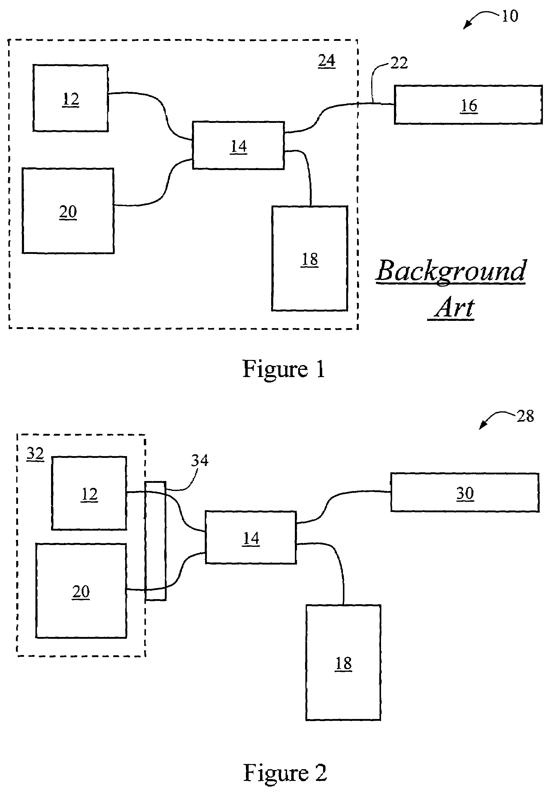
[0036]An optical scanning system incorporating an optical connector according to an embodiment of the present invention is shown generally at 28 in FIG. 2. The components of scanning system 28 are, in some cases, comparable with those of endoscope 10 of FIG. 1, so like reference numerals have been used to indicates like features.

[0037]Scanning system 28, which might be in the form of an endoscope or microscope, includes a laser 12 with 488 nm wavelength output, a light separator in the form of coupler 14, a scanning optical head 30, power monitor 18, and detection unit 20. Laser 12 and detection unit 20 are contained in control box 32.

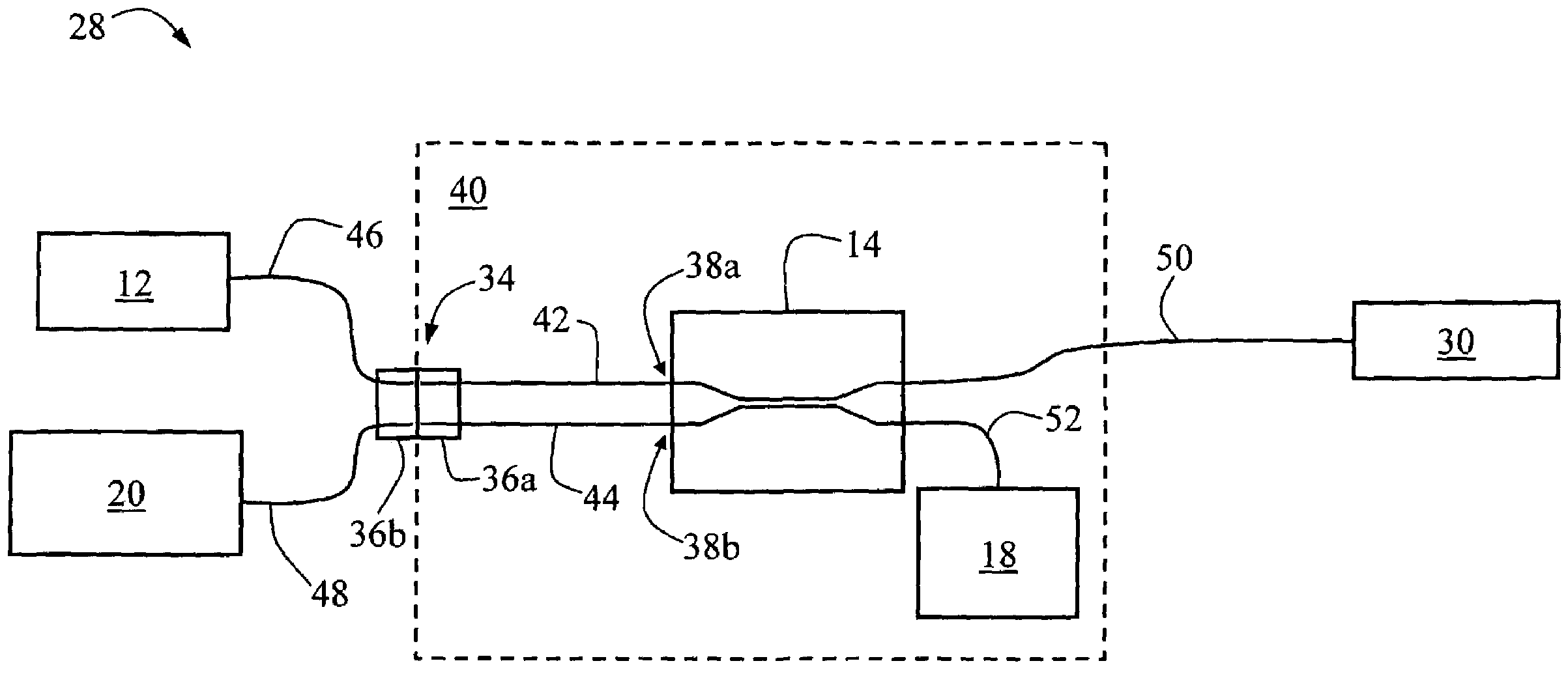
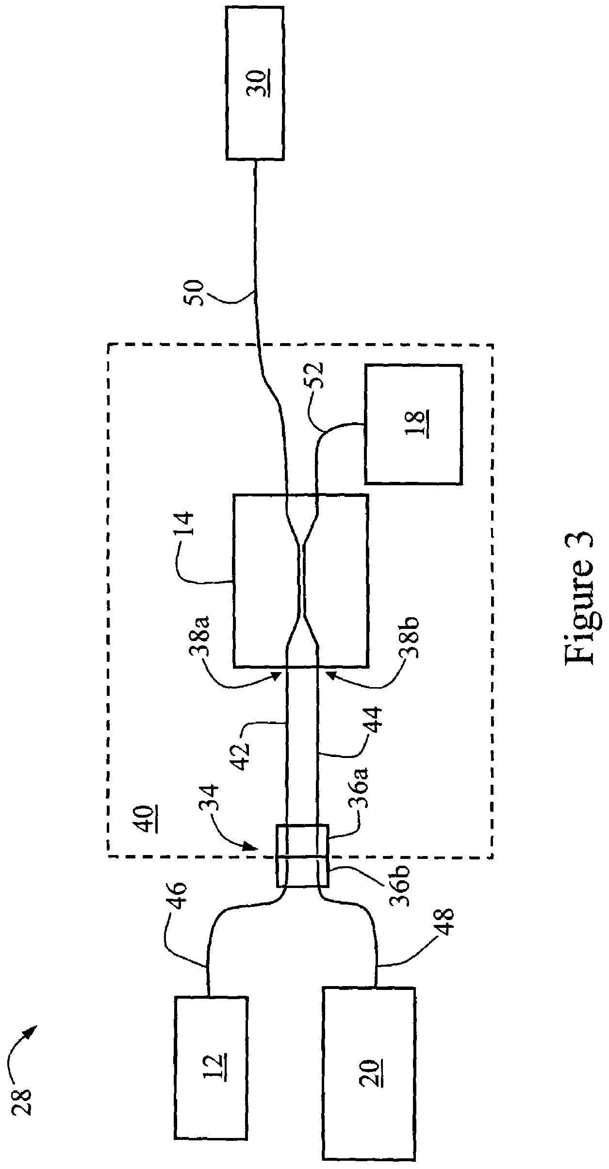
[0038]Scanning system 28 is also provided with an optical connector 34 for connecting the coupler 14 to the control box 32. Referring to FIG. 3, which is a more detailed schematic view of scanning system 28 of FIG. 2, the connector 34 comprises two portions, first portion 36a and second portion 36b. The first portion 36a is coupled to first and second ...


PUM


Abstract

An optical connector for use with a light separator, the optical connector including a first portion and a second portion, the first portion being optically couplable by first optical transmitter to a first input of the light separator and by second optical transmitter to a second input of the light separator. The first and second portions are detachably couplable to couple the first and second optical transmitter to third and fourth optical transmitters, respectively, provided in or coupled to the second portion. The first and second inputs of the light separator can thereby be optically coupled to a first optical instrument coupled to the third optical transmitter and a second optical instrument coupled to the fourth optical transmitter.

Description

RELATED APPLICATIONS[0001]This application is based on and claims the benefit of the filing date of U.S. provisional application Ser. No. 60 / 470,874 filed 16 May 2003, the contents of which is incorporated herein by reference in its entirety.FIELD OF THE INVENTION[0002]The present invention relates to an optical connector, of particular but by no means exclusive application with endoscopes, endomicroscopes, microscopes, colonoscopes and scanning devices for connecting an optical coupler to both a laser and a detector unit.BACKGROUND OF THE INVENTION[0003]An arrangement typical of existing endoscopes is shown schematically at 10 in FIG. 1. The laser 12 provides the excitation light for a fluorescent dye with which a sample has been stained or for reflection from the sample. A light separator in the form of coupler 14 couples laser light from the laser 12 to both endoscope head 16 and a power monitor 18. The power monitor 18 includes a power monitor device, and allows the operator to ...

Claims


Application Information

Patent Timeline
Patent Type & Authority Patents(United States)
IPC IPC(8): G02B6/36G02B6/38A61B1/00A61B19/00G02B6/42G02B21/00G02B23/26
CPCA61B1/00126G02B6/4246G02B6/3885
Inventor PATTIE, ROBERT ALAN
Owner OPTISCAN
Why Eureka
Try Eureka