Touch panel input device

a technology of input device and touch panel, which is applied in the direction of static indicating device, printed circuit aspect, instruments, etc., can solve the problems of short circuit between the contacts of the connector, the inability to vibrate the touch panel to such a degree, and the increase in the number of components, so as to achieve easy connection operation

Inactive Publication Date: 2005-10-06
SMK CORP
View PDF7 Cites 54 Cited by
  • Summary
  • Abstract
  • Description
  • Claims
  • Application Information

AI Technical Summary

Benefits of technology

[0047] In the invention, the four power lead patterns, extending from the pair of piezoelectric plates, can be connected respectively to the corresponding power conductor wires at one concentrated position, and therefore the connecting operation can be effected easily. Particularly, in the process of connecting the power conductor wires by thermocompression welding, the power conductor wires can be connected respectively to the four power lead patterns while applying a uniform pressure thereto, and therefore all of the power conductor wires can be positively connected respectively to the power lead patterns without a variation in the applied pressure.

Problems solved by technology

Therefore, when a high drive voltage was applied between the contacts, there was a fear that the short-circuiting occurred between the contacts of the connector.
However, in the former method, the touch panel can not be vibrated to such a degree as to enable the operator to perceive the vibration.
In the latter method, the number of the component parts increases, and the two kinds of connectors must be prepared, and besides the wiring becomes complicated.

Method used


Image

  • Touch panel input device
  • Touch panel input device
  • Touch panel input device

Examples


first embodiment

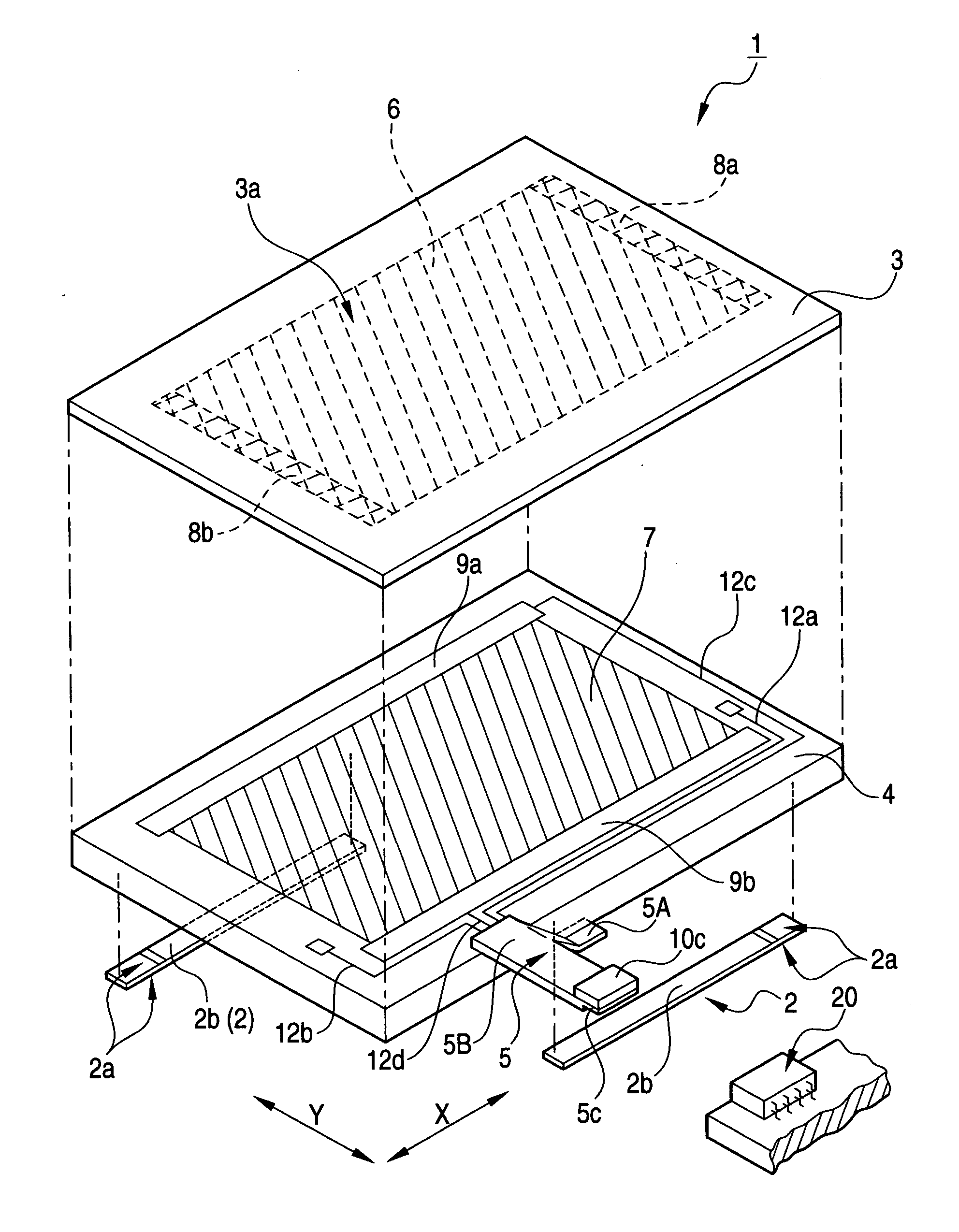
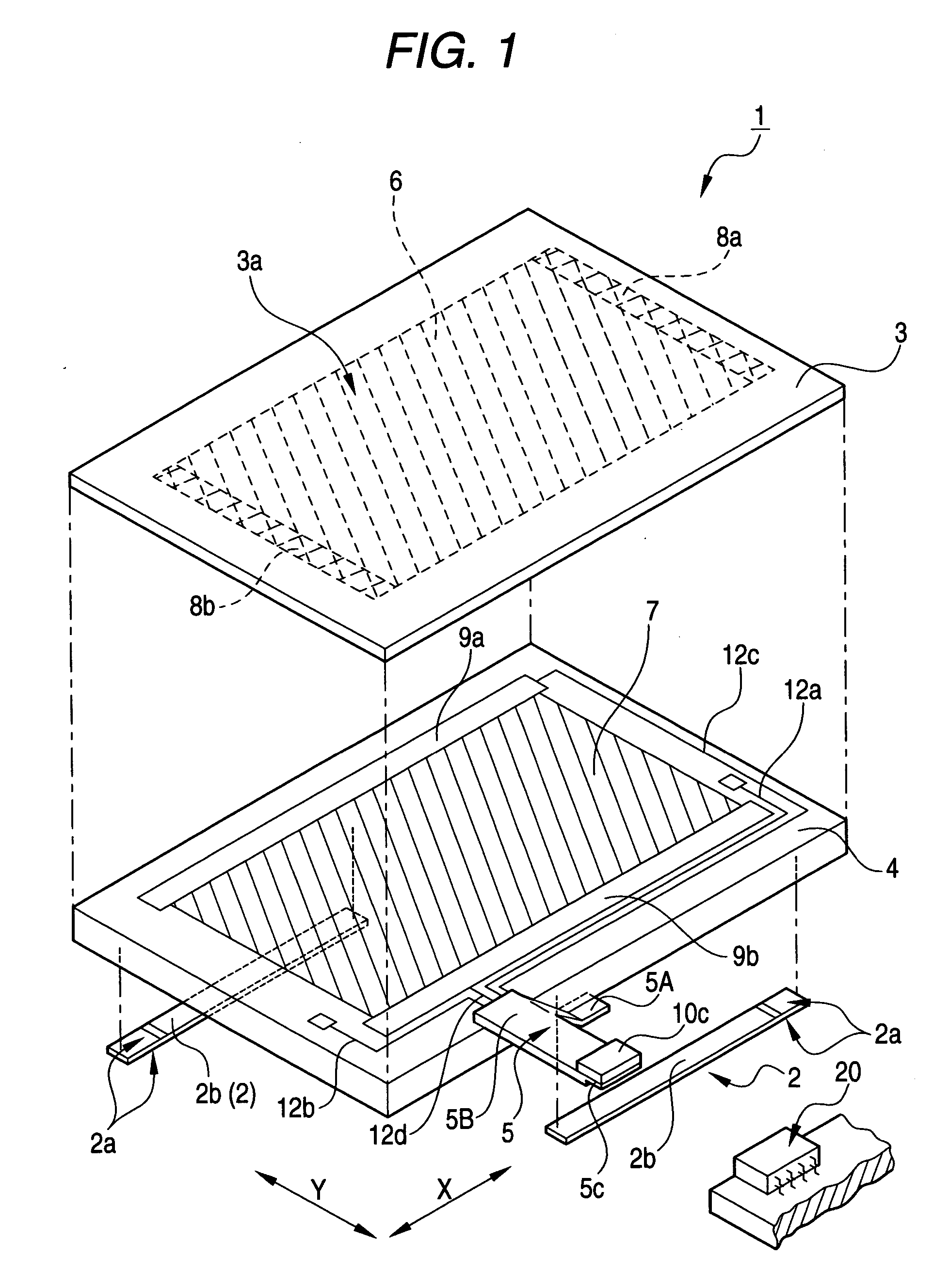
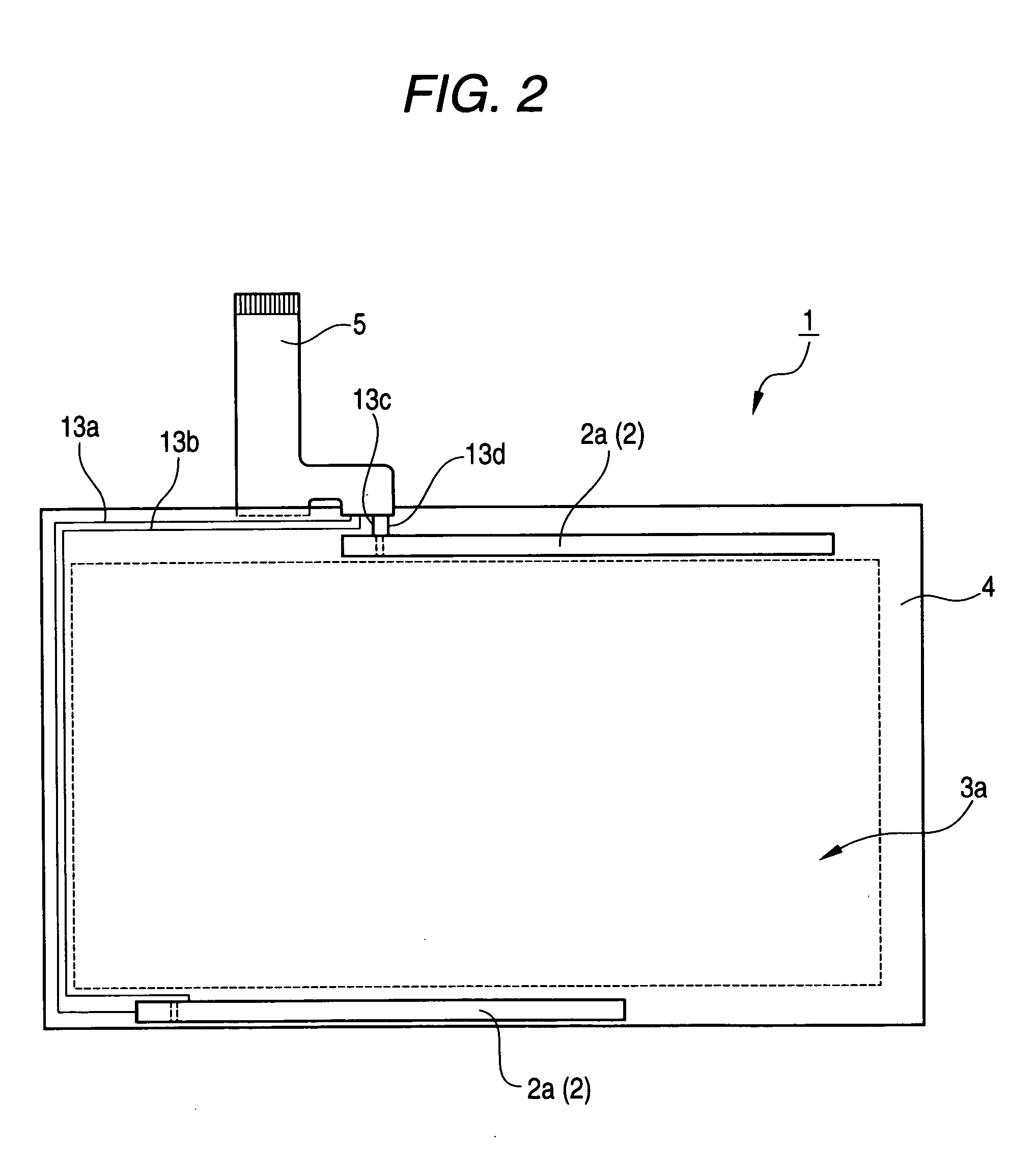
[0055] A first preferred embodiment of a touch panel input device 1 of the present invention will now be described with reference to FIGS. 1 to 4. The touch panel input device 1 according to the embodiment is of the so-called resistance sensitive type in which a touch panel is formed by an operating panel 3 and a support board 4 which are stacked together with a small gap formed therebetween, and conductive layers, each formed of a resistance film of a uniform thickness (in which a uniform potential gradient can be formed), are affixed respectively to opposed surfaces of the operating panel 3 and support board 4. An input operation position is detected from a potential at a position of contact between the conductive layers. FIG. 1 is an exploded, perspective view showing the whole of the touch panel input device 1, FIG. 2 is a bottom view thereof, FIG. 3 is an enlarged perspective view showing a connecting portion for a connector tail 5, and FIGS. 4A, 4B and 4C are a plan view, a si...

second embodiment

[0083] In the touch panel input device 30 of this second embodiment, the present invention can be performed without the need for producing the specially-designed connector tail 5 of the first embodiment in which the pitch of the power conductor wires 15 is twice larger than the pitch of the signal conductor wires 14.

[0084] In the above first and second embodiments, the four power conductor wires 15, 36 of the connector tail 5, 31 are connected respectively to the four corresponding power lead patterns 13, 33 extending from the respective drive electrodes 2a and 2b of the pair of piezoelectric plates 2. However, there can be provided an arrangement in which two power lead patterns (for example, power lead patterns 13a and 13c), connected respectively to one drive electrodes 2a, 2b of the pair of piezoelectric plates 2, are collectively connected to one of a pair of power conductor wires, while two power lead patterns (13b and 13d), connected respectively to the other drive electrode...


PUM


Abstract

A plurality of signal conductor wires connected respectively to signal lead patterns, and a plurality of power conductor wires connected respectively to power lead patterns are formed on a connector tail and are arranged to extend in a leading-out direction. A pitch of the power conductor wires is twice larger than a pitch of the signal conductor wires. A sufficient insulating gap is secured between the adjacent power conductor wires, and therefore there is no fear that the short-circuiting occur even when a high drive voltage is applied.

Description

BACKGROUND OF THE INVENTION [0001] This invention relates to a touch panel input device in which when an input operation is applied to a touch panel, the touch panel is vibrated during this input operation so as to cause the operator to have an input operating feeling, and more particularly to a touch panel input device in which the touch panel is vibrated using a piezoelectric plate. [0002] A touch panel input device is called a digitizer. When an operating area provided on a touch panel is pushed or operated for input purposes by a stylus pen or a finger, this input operation and an input operation position within the operating area are detected, and input detection signal, representing the input operation or the input operation position, is output to an external processing apparatus such as a personal computer. [0003] There are known various touch panel input devices which are classified into the contact-type (as disclosed in JP-UM-A-3-6731), the resistance type ((as disclosed in...

Claims


Application Information

Patent Timeline
Patent Type & Authority Applications(United States)
IPC IPC(8): G06F3/02G06F3/041G06F3/03G06F3/045G09G5/00H05K1/02H05K1/11
CPCG06F3/016G06F3/041H05K2201/09236H05K1/0256H05K1/118G06F3/045G06F3/02
Inventor NAKAYAMA, NAOMIIMAI, KAZUO
Owner SMK CORP
Why Eureka
Try Eureka