Micro trench duct placement

a micro-torch duct and trench technology, applied in the direction of service pipe systems, instruments, mechanical equipment, etc., can solve the problems of large surface destruction, difficult excavation, and difficulty in supplying fiber optic cabling to the many locations,

Inactive Publication Date: 2005-09-01
MCI WORLDCOM INC
View PDF9 Cites 62 Cited by
  • Summary
  • Abstract
  • Description
  • Claims
  • Application Information

AI Technical Summary

Benefits of technology

[0005] According to another aspect consistent with the principles of the invention, an assembly for carrying cable within a trench cut in concrete or asphalt includes a duct comprising a tubular mate

Problems solved by technology

However, provision of fiber optic cabling to the many locations, where it is in demand, has been problematic.
Underground cable placement, though, requires excavation and, often, considerable surface destruction to permit the placement of the fiber optic cabling.
Additionally, when the cable is placed in the ground, i

Method used


Image

  • Micro trench duct placement
  • Micro trench duct placement
  • Micro trench duct placement

Examples


Embodiment Construction

[0019] The following detailed description of the invention refers to the accompanying drawings. The same reference numbers in different drawings may identify the same or similar elements. Also, the following detailed description does not limit the invention. Instead, the scope of the invention is defined by the appended claims and their equivalents.

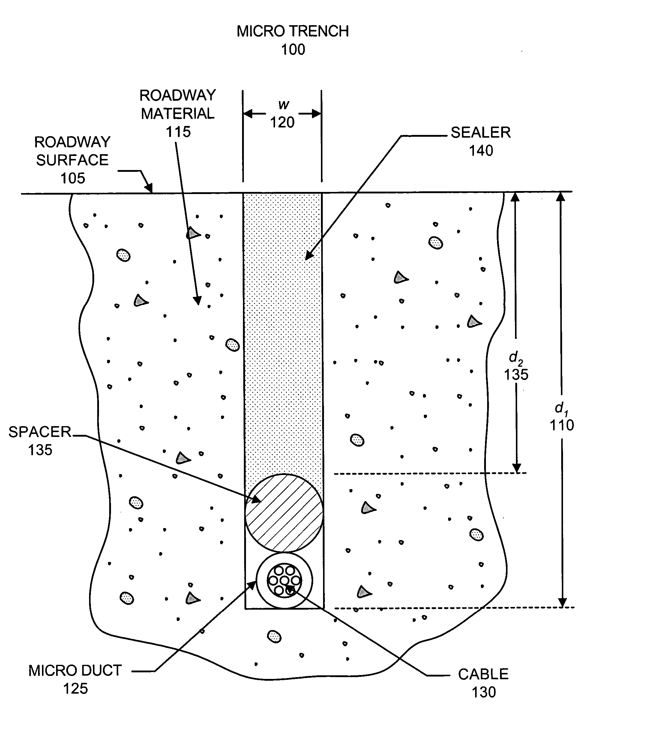
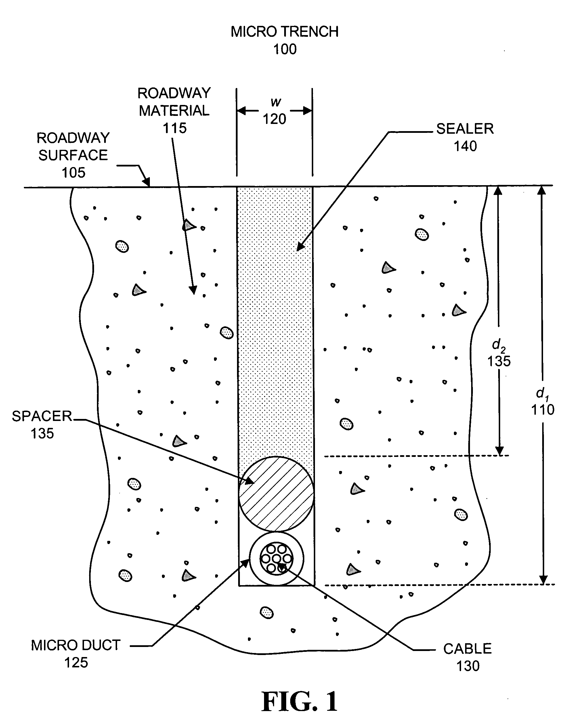
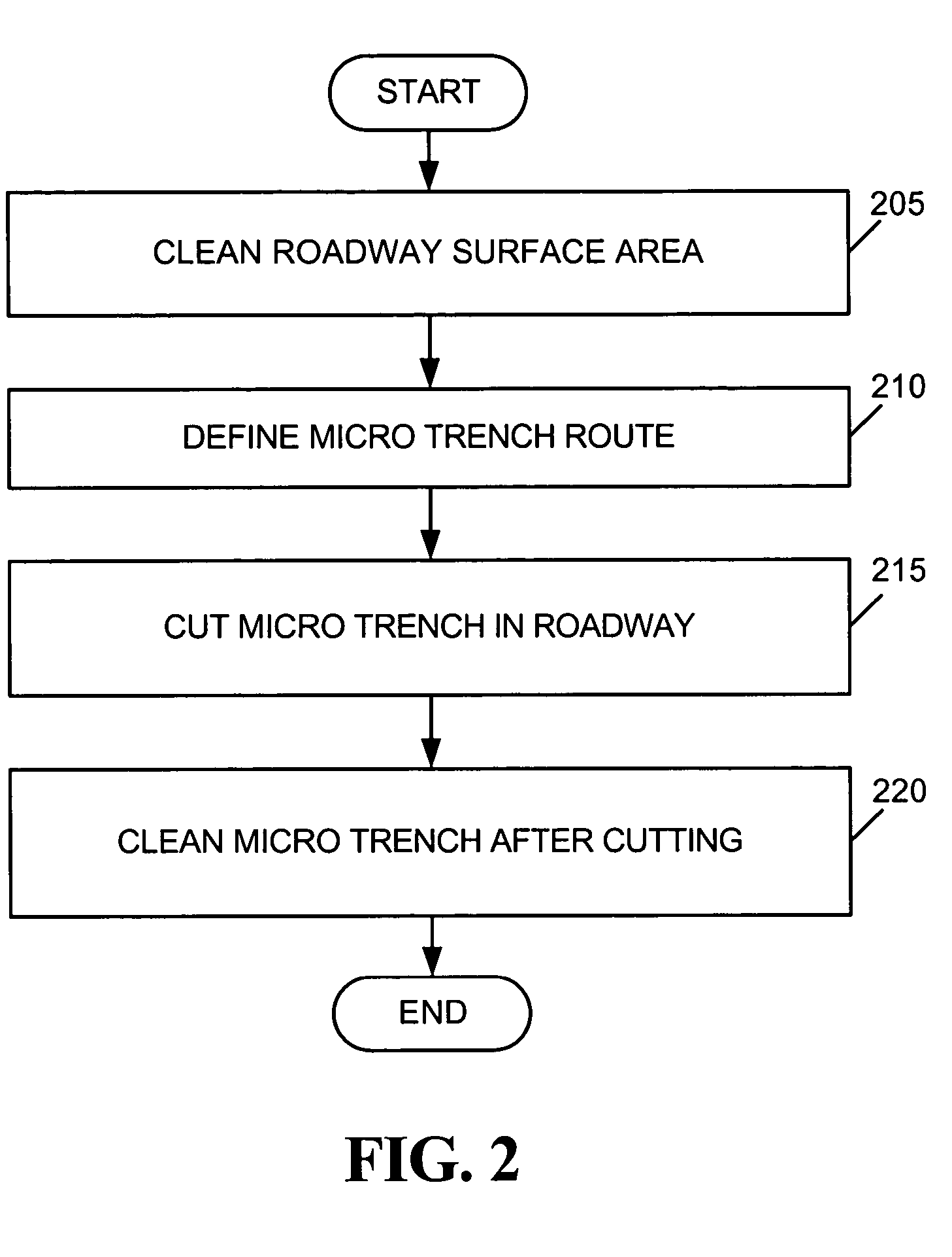
[0020] Methods and assemblies consistent with the present invention enable the placement of subsurface utility cables through the use of subsurface micro trenches and micro ducts, installed in roadway concrete or asphalt, that require minimal surface trenching, permit easy repair of the utility cables, and protect the utility cables from environmental conditions or external events. Consistent with one aspect of the invention, micro trenches may be cut approximately three to four inches into a roadway surface, and a micro duct that includes a high load rating material may be placed into the micro trench for carrying the subsurface utility...


PUM


Abstract

A method of placing cable within concrete or asphalt includes cutting a trench into the concrete or asphalt. The method further includes placing a tubular material having a hollow inner diameter within the trench. The method also includes placing the cable within the tubular material.

Description

FIELD OF THE INVENTION [0001] The present invention relates generally to outside utility cable placement techniques and, more particularly, to utility cable placement using micro trench ducts. BACKGROUND OF THE INVENTION [0002] With the explosion in communication via the Internet in recent years, there has been a corresponding increase in demand for high-speed bandwidth, such as that provided by fiber optic cables. However, provision of fiber optic cabling to the many locations, where it is in demand, has been problematic. Underground provision of fiber optic cabling has been a primary means of providing the cabling to various locations. Underground cable placement, though, requires excavation and, often, considerable surface destruction to permit the placement of the fiber optic cabling. Additionally, when the cable is placed in the ground, it is difficult to repair without having to re-excavate the area so that the cable can be removed. Furthermore, placement of cable directly in ...

Claims


Application Information

Patent Timeline
IPC IPC(8): G02B6/50
CPCG02B6/504
Inventor PURCELL, STEVEN L.
Owner MCI WORLDCOM INC
Why Eureka
Try Eureka