Automated airport luggage system

a luggage system and automatic technology, applied in the direction of steering control, braking system, non-vehicle mounted steering control, etc., can solve the problems of interfering with each other's luggage, not being large enough for luggage, and difficult to find the car

Inactive Publication Date: 2005-09-01
BEN EZRA ELISHAH
View PDF8 Cites 29 Cited by
  • Summary
  • Abstract
  • Description
  • Claims
  • Application Information

AI Technical Summary

Benefits of technology

[0049] Further in accordance with a preferred embodiment of the present invention, the track includes merging junctions at which wagons may be collected from different locations. is Additionally, in accordance with a preferred embodiment of the present invention, the external-wall sections may be selectably lowered for allowing the wagon to be removed from the track, and for allowing the wagon to be mounted on the track.
[0050] Further in accordance with a preferred embodiment of the present invention, at least one track of the plurality of tracks is operable as a multi-lane track, having dividing-wall sections, along the x-axis, between lanes, and having dividing-wall sections, along a y-axis, across lanes, wherein the dividing-wall sections are arranged to be raised a

Problems solved by technology

Carriages may be hard to find, or they may not be large enough for the luggage.
At luggage pick-up zones, passengers crowd around conveyer belts, blocking each other's view, and interfering with each other's attempt to retrieve their belongings.
However, a disadvantage of this system is that it provides a baggage handling method only for part of

Method used


Image

  • Automated airport luggage system
  • Automated airport luggage system
  • Automated airport luggage system

Examples


first embodiment

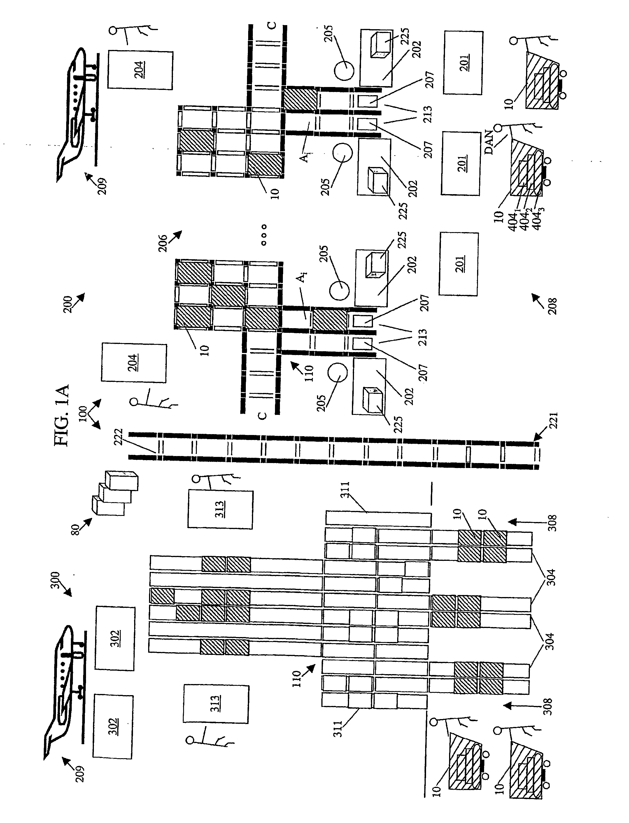
[0346] Reference is now made to FIGS. 16A-16C, which together schematically illustrate a track 600 of track system 110, for moving wagons 10 along it, in arrival area 300, in accordance with the present invention. In a sense, the movement of wagons along track system 110 is simpler on arrival than during departure, since on arrival, all pieces of luggage from plane 209 are to be moved to the same luggage pick-up area 304, and it appears that no sorting is necessary.

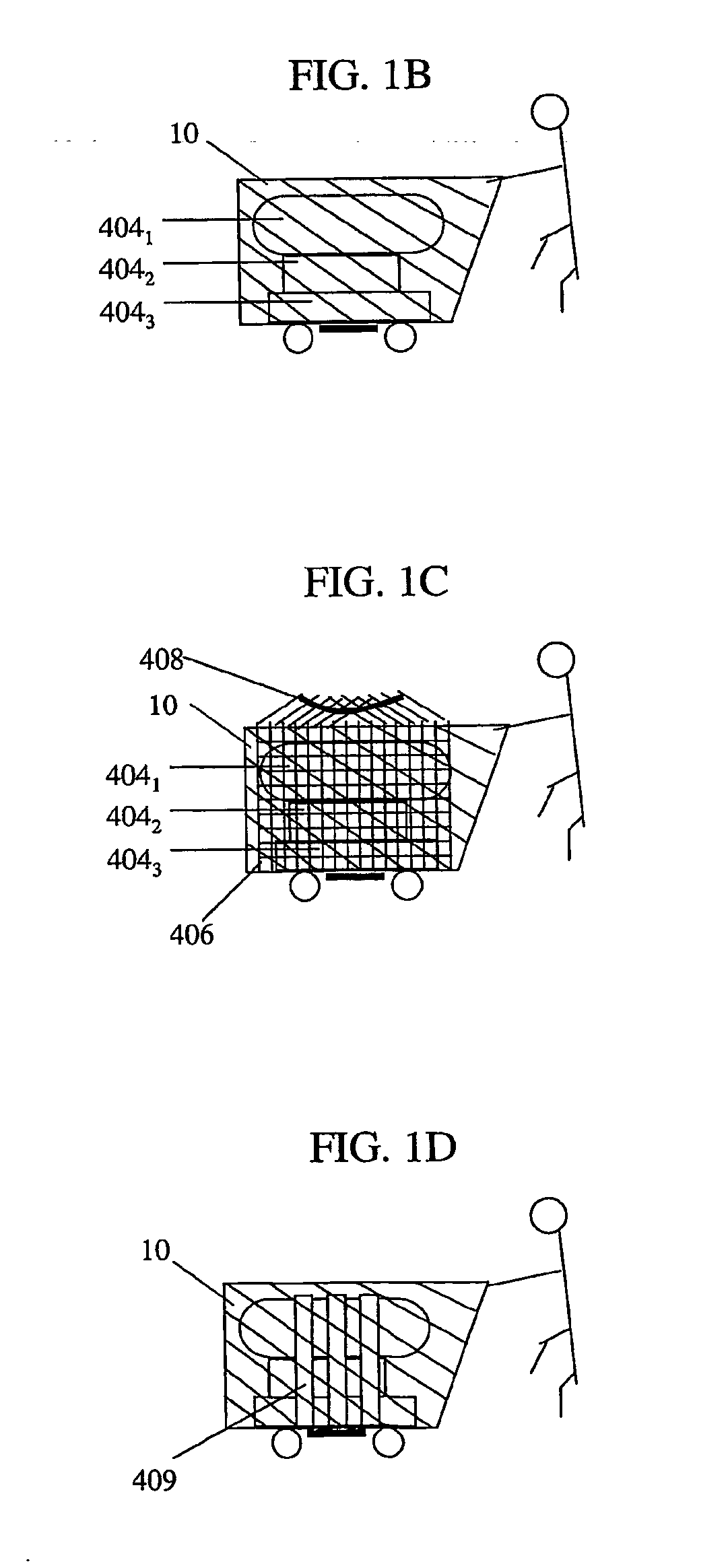
[0347] However, it is desirable that passenger Dan will receive his three pieces of luggage together, so that where wagons 10 are used, it is desirable that luggage 4041, 4042, and 4043 will all be on the same wagon 10, at arrival area 300. Where sacs 406 or straps 409 are used to form a single piece of luggage from 4041, 4042, and 4043, this requirement is already fulfilled by the use of sacs 406 or straps 409.

[0348] As seen in FIG. 16A, arrival area 300 includes airplane-unloading zone 302 at a distal end 602 of track ...

second embodiment

[0383] Reference is now made to FIGS. 17A and 17B, which together schematically illustrate track system 610, and a system of trays 660, arranged for sorting pieces of luggage, by passenger, into wagons 10, in accordance with the present invention. In this way, passenger Dan will receive his three pieces of luggage, 4041, 4042, and 4043 together, on a single wagon 10, at the destination airport.

[0384] In jumbo planes, luggage is generally arranged in containers, wherein each container includes, on the average, 40 pieces of luggage. Thus, although several hundred passengers may have flown in airplane 209, the airplane in which passenger Dan flew, and although the number of pieces of luggage is generally 160% greater than the number of passengers, the luggage in each container belongs to only about 25 people. Preferably, the several pieces of luggage from a single wagon 10 are loaded onto a single container. Thus, the luggage in each container needs to be sorted only amongst about 25 w...

third embodiment

[0401] Reference is now made to FIGS. 18A-18E, which together, schematically illustrate a tray means 700 for automatically sorting and loading luggage onto wagons 10, located in loading tracks 615 and 613, in accordance with the present invention.

[0402] As seen in FIG. 18A, tray 700 is boat-like in shape and includes a bow-like proximal end 674 and a stem-like distal end 672, wherein proximal and distal are described with respect to wagon 10. Tray 700 further includes a bottom side 676 and a top side 678. Additionally, tray 700 includes sides 680, a bottom 690, a back 689 at distal end 672, and a slanted swinging door 694, arranged on hinges 696, at proximal end 674.

[0403] Furthermore, tray 700 includes two slanted telescopic bars 692, parallel to slanted swinging door 694, at proximal end 674. Slanted telescopic bars 692 support a top 698 and are arranged for telescopically extending and contracting in length, by a driver 686, preferably located within one of slanted telescopic ba...


PUM


Abstract

An airport terminal (100) has a department area (200) which includes at least one, and preferably a plurality of check-in counters (202), at least one, and preferably a plurality of airplane-loading zones (204), and a track system (110), arranged for the movement of wagons (10). Wagon (10) is for automatically transporting and sorting luggage, responsive to commands from a computerized management system (80). The wagon (10) includes a rigid frame for containing the luggage. The frame includes four sides and a double bottom having an upper plate, a lower plate, and an internal compartment.

Description

FIELD OF THE INVENTION [0001] The present invention relates generally to systems for transporting luggage and in particular to an automated airport luggage system. BACKGROUND OF THE INVENTION [0002] Many people are familiar with luggage-related difficulties that are associated with air travel. Carriages may be hard to find, or they may not be large enough for the luggage. At luggage pick-up zones, passengers crowd around conveyer belts, blocking each other's view, and interfering with each other's attempt to retrieve their belongings. Most annoying, sometimes a passenger may be flying to one destination, while his or her piece of luggage is sent to another. [0003] U.S. Pat. No. 5,793,639 to Yamazaki, “Baggage Receiving and Handling Method in Airport, and Baggage Automatic Handling Apparatus,” 1998, describes an airport baggage receiving, identifying and handling method. The method includes providing identification information of the passenger and the baggage separately and with resp...

Claims


Application Information

Patent Timeline
IPC IPC(8): B07C5/36B64F1/36G06K17/00
CPCB07C5/36B64F1/366G06K2017/0048G06K17/00B64F1/368
Inventor BEN-EZRA, ELISHAH
Owner BEN EZRA ELISHAH
Why Eureka
Try Eureka