
Structural joint connection providing blast resistance and a beam-to-beam connection resistant to moments, tension and torsion across a column

a technology of structural joint connection and beam, which is applied in the direction of shock-proofing, building roofs, building components, etc., can solve the problems of affecting the stability of the beam, the insufficient and unreliable beam-to-column joint connection, and the inability to meet the demands of vertical moment demand, so as to mitigate the likelihood of progressive collapse of the entire beam

Active Publication Date: 2005-09-22
MITEK HLDG INC
View PDF13 Cites 59 Cited by
  • Summary
  • Abstract
  • Description
  • Claims
  • Application Information

AI Technical Summary

Benefits of technology

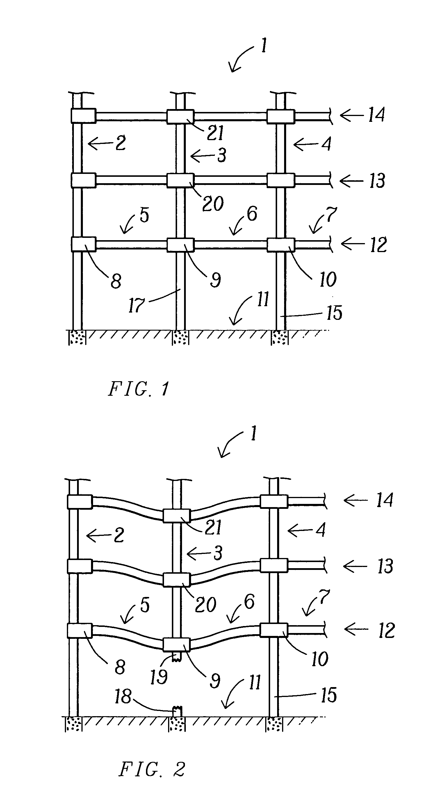
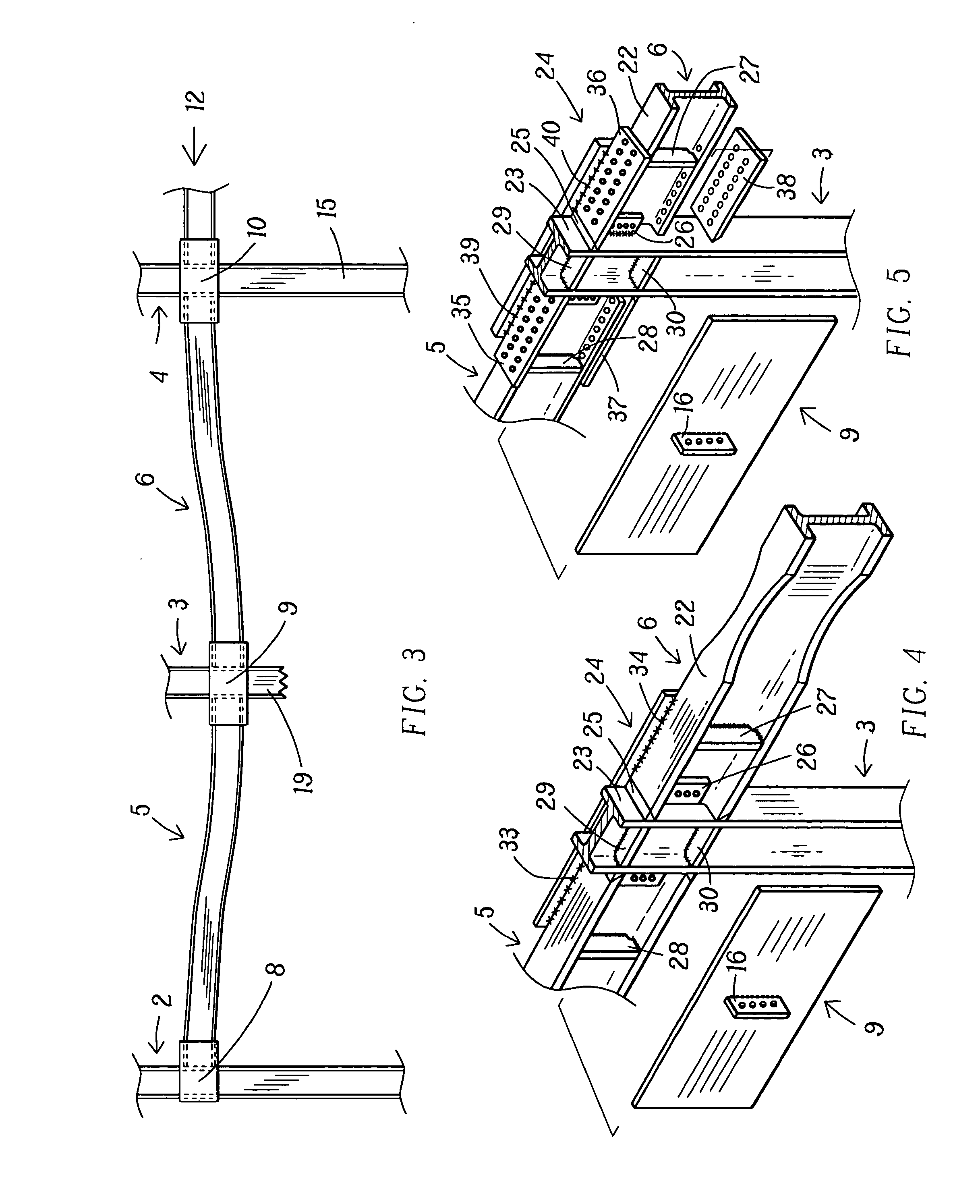
[0023] Given the violent removal, during a terrorist attack, for example, of a column positioned between two adjacent beams, the strength of this invention's beam-to-beam gusset plates connection across that column, independent of that column's demise or damaged state, is capable of resisting the ultimate tensile and flexural strength demands, including their interactive effects, from the beams joined by the gusset plates, which beams thereby remain joined and effective. Such extreme tension and moment demands result from the creation of, and gravity loading of, a “double-span” condition of the said two joined beams located on either side of the removed or damaged column, which “double-span” condition, in turn, exerts tremendous tensile pull and vertical moment demand on adjacent beams-to-column joint connections.
[0052] It is another object of this invention to provide a structural beam-to-beam connection which remains effective after violent loss of column support or loss of beam-to column joint connection.

Problems solved by technology

It is recognized that upon blast or explosion or other disastrous event, support from the column may be partially or totally lost.
This may be due to loss of the column and / or partial or total failure of the beams-to-column joint connections.
In either event, the beams-to-column joint connection is then insufficient and unreliable.
Such extreme tension and moment demands result from the creation of, and gravity loading of, a “double-span” condition of the said two joined beams located on either side of the removed or damaged column, which “double-span” condition, in turn, exerts tremendous tensile pull and vertical moment demand on adjacent beams-to-column joint connections.

Method used


Image

  • Structural joint connection providing blast resistance and a beam-to-beam connection resistant to moments, tension and torsion across a column
  • Structural joint connection providing blast resistance and a beam-to-beam connection resistant to moments, tension and torsion across a column
  • Structural joint connection providing blast resistance and a beam-to-beam connection resistant to moments, tension and torsion across a column

Examples


Embodiment Construction

[0076] The structural steel commonly used in steel frameworks is produced in conformance with standard A-36, A-572 and A-992 specifications. High strength aluminum and other high-strength metals might be found suitable for use in this invention under some circumstances. It is recognized that other materials, particularly in the gusset plates and, possibly, in the joint connections, might be used. For example, in the gusset plates other materials and shapes might be used. There would be required of such gusset plates, that they each be a weldable structure extending along one side of both beams, and having strength equivalent to structural steel plate. The cover plates would be required, in some cases to be weldable, in other cases drillable for bolt or rivet holes. They, too, would have to have the strength equivalent to a similar structural steel plate.

[0077] Commonly shown in the drawings herein are fillet welds and full-penetration, single bevel groove welds. The mention or illu...


PUM


Abstract

At a beams-to-column joint connection of two beams to a column, in which the joint connection comprises both a gravity load-carrying connection and a moment-resisting connection, there is added a beam-to-beam connection across the column, using two gusset plates, facing each other, on opposite sides of the joint connection. The gusset plates, which are not connected to the column in a moment-resisting connection, connect the two beams, in a tension and moment-resisting connection with respect to each other, by longitudinal welds between the gusset plates and the beams, and provide the capability of withstanding disastrous events, including loss of column support and / or loss of integrity of the beams-to-column joint connection and severe torsional and lateral inelastic deformation due to direct blast pressure. When subjected to such violent conditions and upon loss of column support, and, the likely loss of integrity of the beams-to-column joint connection, the two beams and two gusset plates provide independent beam-to-beam structural continuity, causing the two beams to act as one long beam, or, in other words, a “double-span” condition is created. Such beam-to-beam connection is capable of carrying the tension, torsional and moment loads placed upon the beams, to the ultimate capacity of the beams. Inasmuch as a gusset plate is disposed on each side of the beams-to-column joint connections, substantial shielding of those connections against blast and impact forces is also achieved.

Description

BACKGROUND OF THE INVENTION [0001] Buildings, towers and similarly heavy structures commonly are built on and around a steel framework. A primary element of the steel framework is the joint connection of the beams to the column. Gusset plates have been used to provide a superior beams-to-column, moment-resisting joint connection, as set forth in my related U.S. Pat. No. 5,660,017 entitled Steel Moment Resisting Frame Beam-to-Column Connections. A brace, which further strengthened the steel framework, was later added to that joint connection by connecting a brace or braces to the gusset plates, as set forth in my U.S. Pat. No. 6,516,583, entitled Gusset Plate Connections for Structural Braced Systems. Additional, related patents issued to me are U.S. Pat. No. 6,138,427 for Moment Resisting, Beam-to-Column Connection and U.S. Pat. No. 6,591,573 for Gusset Plates Connection of Beam-to-column. [0002] The above patents teach placing a pair of gusset plates opposite each other, on opposit...

Claims


Application Information

Patent Timeline
IPC IPC(8): E04B1/00E04B1/24E04B1/92E04H9/06
CPCE04B1/24E04B1/92E04B2001/2415E04H9/06E04B2001/2445E04B2001/2448E04B2001/2496E04B2001/2442
Inventor HOUGHTON, DAVID L.
Owner MITEK HLDG INC
Learn More