
System for organizing and displaying registered images

a registered image and image technology, applied in the field of imaging, can solve the problems of not displaying affecting the usefulness of such images as currently presented, and xiong does not display constituent images in their unmodified form, so as to enhance the user's perception of the context of any selected image, facilitate and rapid orient images, and slow down user viewing experience

Active Publication Date: 2005-09-22
VANBREE KEN
View PDF13 Cites 17 Cited by
  • Summary
  • Abstract
  • Description
  • Claims
  • Application Information

AI Technical Summary

Benefits of technology

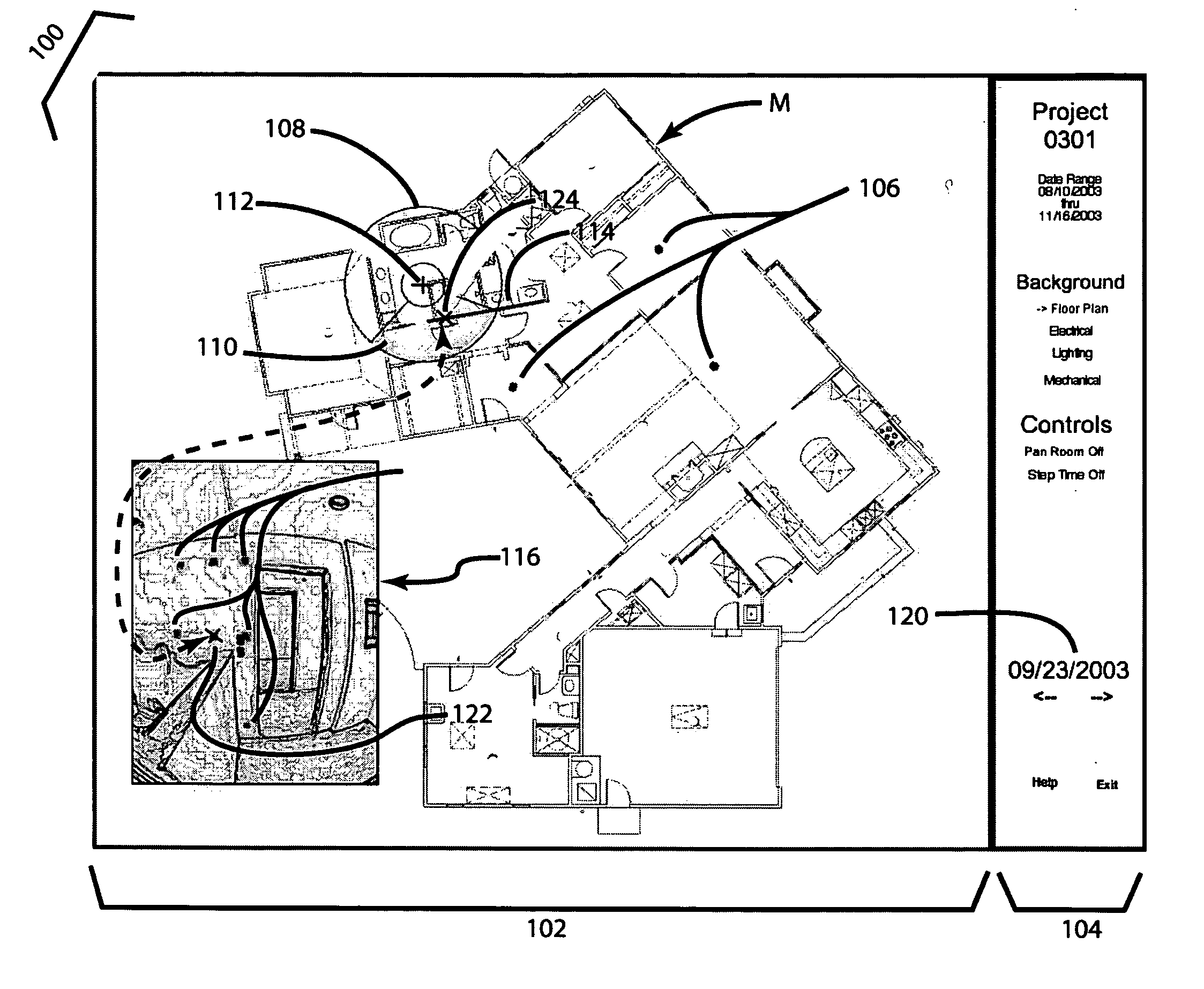
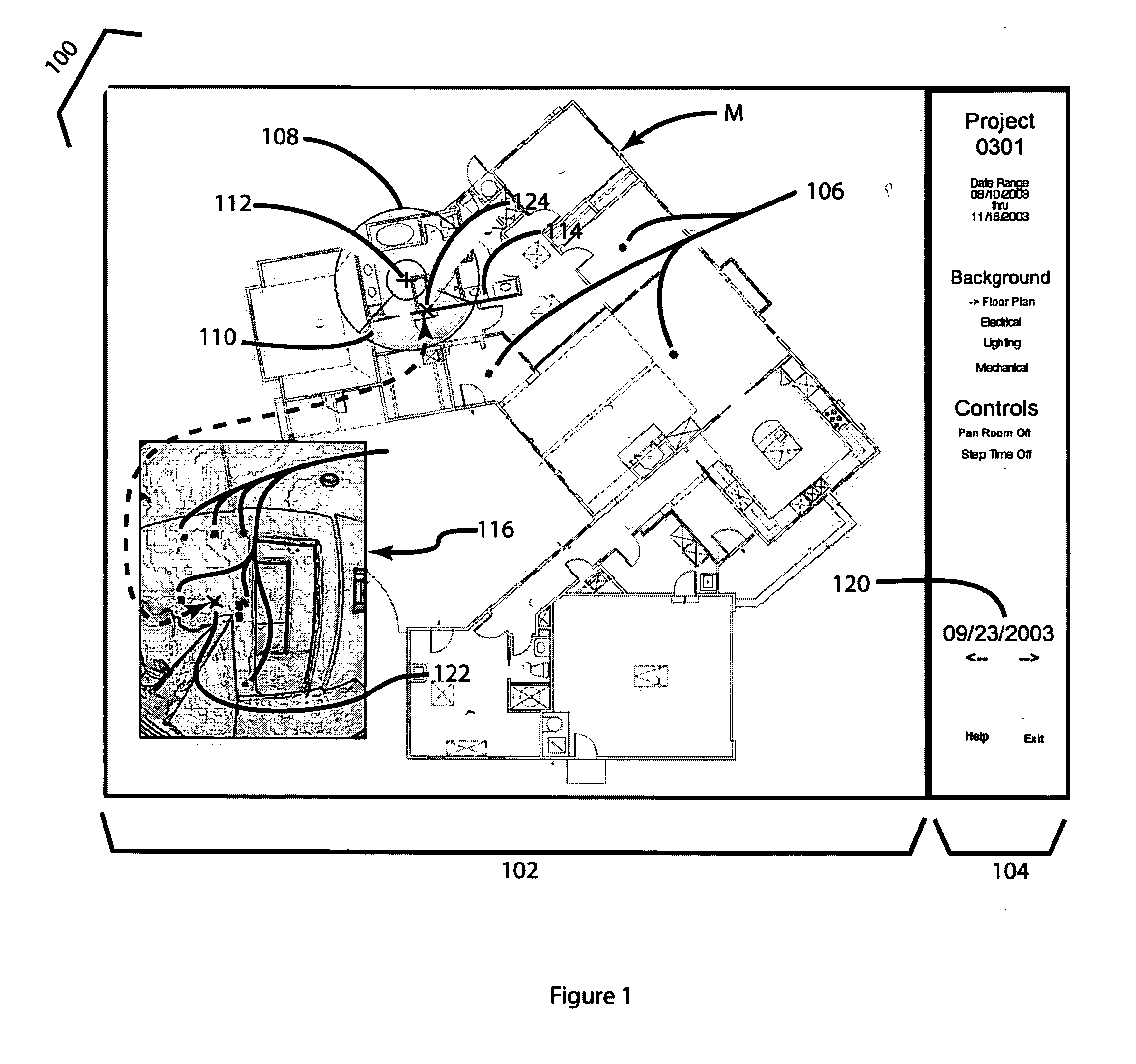
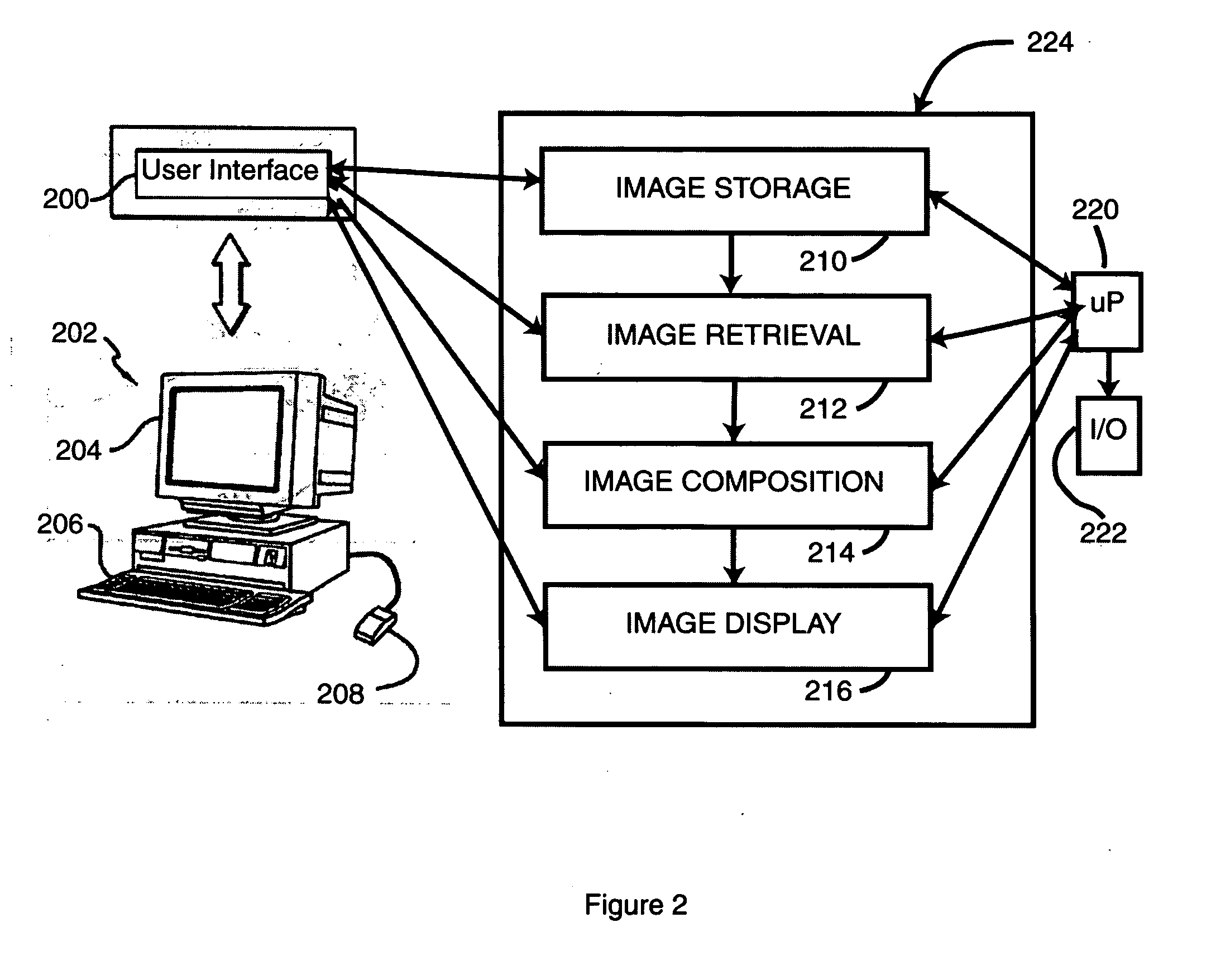
[0009] The invention provides an image management system enabling rapid and easy retrieval and display of multiple images or collections of images, where such images are spatially related and may also be related according to non-spatial parameters. The mode or modality of the imaging device or the time of imaging, or both, may be, for example, non-spatial parameters associated with the imaging data. The inventive system provides a user interface operably associated with computational modules capable of image storage, image retrieval, image composition, and image display. The user can connect with the user interface by a variety of devices (PC. PDA, any mobile device or any other instrument with display capability), and the user interface may output a user interface display. The inventive system user interface display has an image display area and an information and control area, both contributing to the user's quick comprehension of the spatial and temporal relationship of the images selected for display. The user interface display according to the present invention is dynamically manipulable, enabling the user to select a stored map (a construction blueprint in the preferred embodiment) from the control panel, and the map appears in the image display area. The user may point and click or otherwise interact with the user interface display to simultaneously display both a feature (ex. a room wall) as well as a visual indication of the point from which the image was created, called the “image locator” (i.e. where the camera / imaging device was positioned at the time of image creation) and the visual indication of the direction the camera / imaging device was pointing when the image was created. The user can simply move around the map and other images and portions of images taken from the same perspective are seamlessly viewable. Thus, for example, a wall can be viewed from framing, through electrical installation, through drywall and finishing on the dynamically manipulable interface display.
[0011] The invention provides a means for organizing and presenting images through the user interface display in a manner that integrates detailed information concerning any image with respect to the image sourcing environment (the position from which the image was generated) and the neighborhood in which the image sourcing device was situated. For example, the spatial relationship between a selected image retrieved by the user and neighboring images will appear on the interface display by means of the image locater within the image display area on the user interface display. The image locater assists the user by visually contextualizing the selected image within a map and showing the neighborhood or surroundings in which the image was taken.
[0012] The invention also provides for retrieving, viewing and comparing images taken at the same or different times from a selected perspective (image sourcing position) without extensive calculations slowing down the user's viewing experience. This is facilitated by use of “zone of focus” calculation and storage of calculation results for each image, establishing the orientation of the image source device with respect to each stored image.
[0013] The invention also provides a means for combining multiple viewing modes (for example a composite (FIG. 4) in conjunction with a transparency mode(not shown)). Further, different image types (e.g. visual and thermographic) may be overlaid and displayed on user interface display—image display area. In all of these modes or combinations of image display, the dynamically manipulable user interface display operates to easily and rapidly orient images on the selected map or blueprint, to indicate the image locater, and thus enhance the users perception of the context of any selected image.

Problems solved by technology

Significant limitations exist on the usefulness of such images as currently presented.
However, Xiong does not display constituent images in their unmodified form, and does not relate images to their environment.
Although Kumar, et al teaches producing a distortion free composite of images taken at the same point in time, it does not teach producing composite images from constituent images, each image from the same imaging point, taken at multiple points in time.
Moreover, available systems used for organizing and displaying high-quality panoramic sequences require a significant amount of computation (and, consequently, computer processing run time) in order to generate a composite image from a sequence of images.
The resulting blended image suffers loss of detail from contributing images.
Such loss of detail hinders generating a good model of the structures shown in the images.
Furthermore, current panoramic image viewers cannot provide registered time-sequential images (that is, images taken from the same imaging point or what is referred to as “perspective”) at times that differ by days, months, or years.

Method used


Image

  • System for organizing and displaying registered images
  • System for organizing and displaying registered images
  • System for organizing and displaying registered images

Examples


Embodiment Construction

[0021] Although the discussion of the preferred embodiment and the accompanying figures may use the word “camera” or related terms, it is intended that “camera” and related terms mean any image sourcing device, that is to say, any device capable of imaging some aspect of interest, whether operable on visible light, non-visible radiation, temperature, bio-mass sensor, or any other image-able feature amenable to an image sourcing device. Although general in teaching, the invention herein described is useful in conjunction with that described in U.S. patent application Ser. No. 10 / 811,019 filed Mar. 26, 2004 entitled “System for Accurately Repositioning Imaging Devices”.

[0022] Referring to FIG. 1, an exemplar screen of the user display interface illustrates one embodiment of the present invention. The user interface display 100 (also referred to herein as a dynamic display) provides two areas: the image display area 102 and the information and control area 104. The information and con...


PUM


Abstract

This invention relates to a system for organizing, storing, retrieving and displaying spatially related images where such images may also be relatable within time or image modality parameters. The system includes a dynamically manipulable user interface capable of visually depicting one or more images in a registerable manner, and also depicting the orientation of the image or images in relation to the surrounding neighborhood. The inventive system provides for display of panoramic image sequences consisting of multiple rows with multiple images per row, or image sequences consisting of only a single image. In a preferred embodiment, images taken from the same perspective at different times can be overlaid, and the user manipulates the display to perform real-time compare and contrast between images. In an alternate embodiment, the registered images include those created by means of different imaging modes or modalities such as, for example, visible light images and thermographic images.

Description

CROSS REFERENCE TO RELATED APPLICATIONS [0001] This Application is related to provisional application 60 / 552,850 filed Dec. 24, 2003, the entirety of which is incorporated by this reference, and claims priority therefrom.GOVERNMENT FUNDING [0002] Not applicable. BACKGROUND [0003] This invention relates to imaging, and more particularly to the spatial and temporal organization of images and related image data. [0004] Panoramic images have been used for many years to generate both high quality printed images, and immersive images that can be viewed and manipulated through a user interface. Linked panoramic images are available in a variety of formats that allow, for example, a potential homebuyer to do a “virtual walkthrough” of a home through a web-based user interface. Significant limitations exist on the usefulness of such images as currently presented. [0005] For example, U.S. Pat. No. 6,359,617 (Xiong) teaches algorithms for blending rectilinear images into virtual reality panora...

Claims


Application Information

Patent Timeline
Patent Type & Authority Applications(United States)
IPC IPC(8): G06F3/00G06T5/50G06T7/00
CPCG06T5/50G06T2207/20221G06T2200/24G06T7/0018G06T7/80
Inventor BREE, KEN VAN
Owner VANBREE KEN
Learn More