Sliding element

a sliding element and sliding face technology, applied in the direction of engine seals, mechanical devices, engine components, etc., can solve the problems of inability to provide the fluid with significant pumping capability, inability to prevent fluid leakage, and damage to the seal capability, so as to improve the seal capability and reduce the friction coefficient of the sliding face.

Inactive Publication Date: 2005-09-29
EAGLE INDS
View PDF8 Cites 57 Cited by
  • Summary
  • Abstract
  • Description
  • Claims
  • Application Information

AI Technical Summary

Problems solved by technology

This is another cause of damage to the seal capability.
That is, the fluid leakage can hardly be prevented.
In particular, the low-pressure spiral grooves 202 thus arranged, spiral curves defined in the region formed by the two radii R1 and R2, cannot provide the fluid with a significant pumping capability.
In addition, a very small depth of groove such as no more than 1 micrometer imposes difficulties on accurate fabrication of the grooves and thereby affects resulting seal capability thereof.

Method used


Image

  • Sliding element
  • Sliding element
  • Sliding element

Examples


example 1

A. Examples of the Sliding Elements Related to the Present Invention.

[0082] 1) Rotary Sliding Elements 1 of the Present Invention are Shown in FIG. 6 through FIG. 17. Stated Earlier. [0083] (A) Example 1-A and example 1-B are referred to as example 1. [0084] (B) Example 2-A and example 2-B are referred to as example 2. [0085] (C) Example 3-A and example 3-B are referred to as example 3. [0086] (D) Example 4-A and example 4-B are referred to as example 4. [0087] (E) Example 5-A and example 5-B are referred to as example 5.

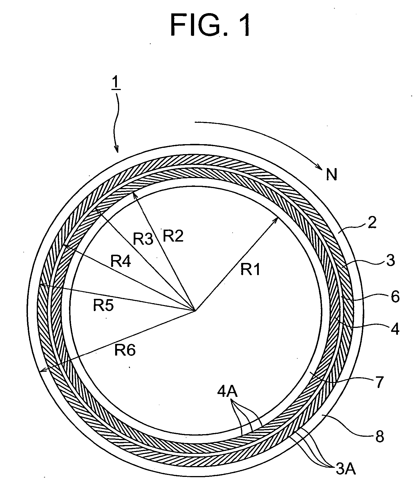
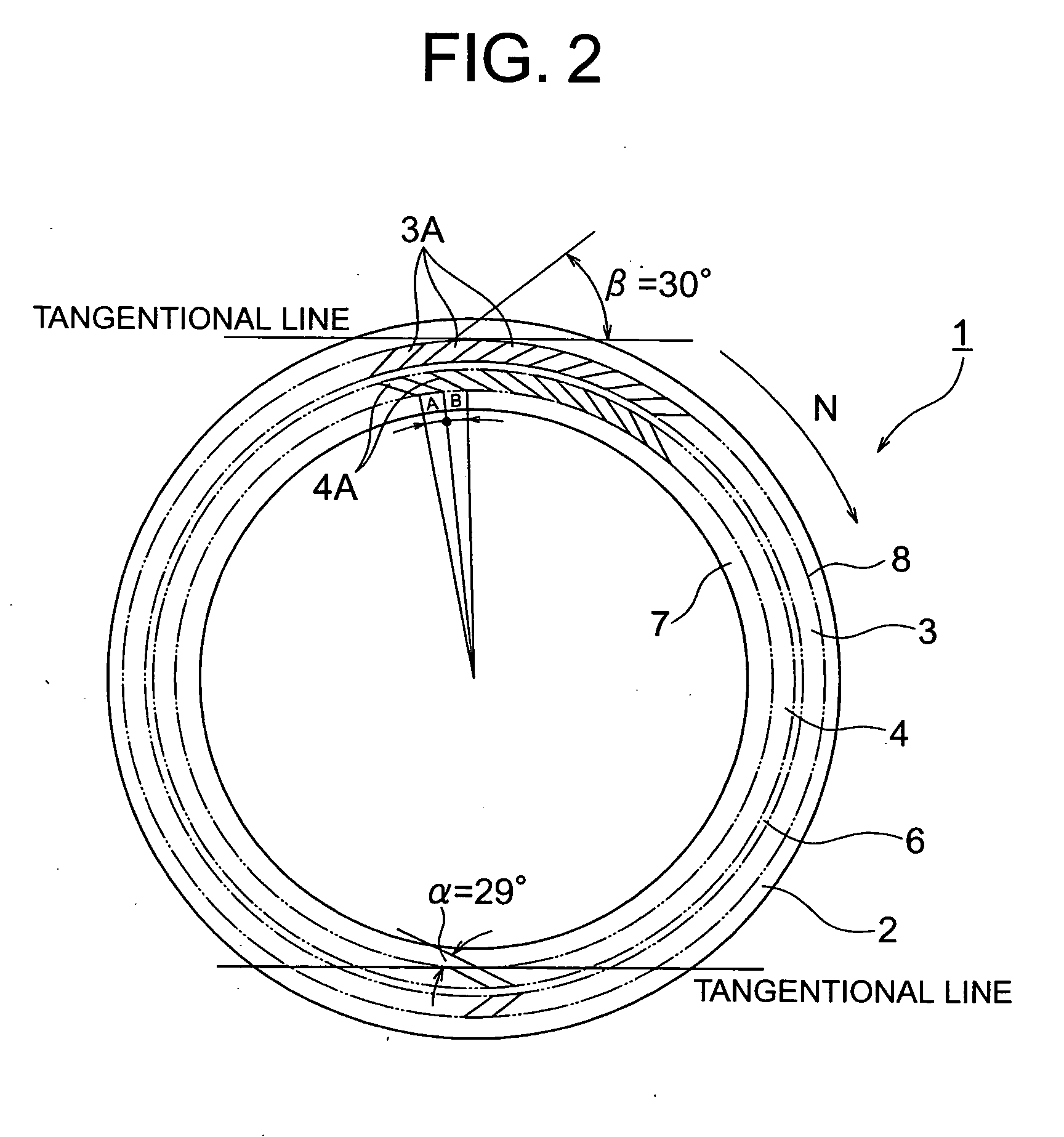
Experiments were conducted with the above sliding elements 1. An opposed stationary sliding element which comes into sealing contact with the above rotary sliding element 1 has a flat sliding face being made of silicon carbide (a pair of the sliding faces in contact should be referred to FIG. 18). Note that a form of the individual dimple sections 4A, 3A of the sliding face 2 is based on those given in FIG. 2, FIG. 3, FIG. 5.

[0088] 2) The Sliding Element 1 is T...


PUM


Abstract

A primary objective of a sliding element of the present invention is to decrease a friction coefficient of the sliding face and to improve seal performance thereof. The sliding element comprises a first dam section (6) which is configured in an annular form on the sliding face (2), a second dimple section (3A) which has a form of a narrow groove and makes an inclination angle (α) being measured from the dam section (6) in a direction of rotation pointing toward the sealed fluid, a suction means (3) which includes an annularly arranged array of the second dimple sections (3A), a first dimple section (4A) which has a form of a narrow groove and makes an inclination angle (α) being measured from the dam section (6) in a direction of rotation pointing an opposite direction relative to the suction means (3), a discharge means (4) which includes an annularly arranged array of the first dimple sections (4A), and a seal face (7) which is disposed in a peripheral surface adjacent to the discharge means (4) and in the opposite side relative to the dam section (6).

Description

BACKGROUND OF THE INVENTION [0001] 1. Field of the Invention [0002] The present invention relates generally to a technical domain of a sliding element engaging a relative rotational motion. More particularly, the invention relates to a sliding element which reduces a friction coefficient on the sliding face and prevents a sealed fluid from leaking from the sliding face. [0003] 2. Description of the Related Art [0004] There has been an increasing demand for a variety of machines nowadays which involve a high-speed rotary shaft as well as a high-pressure fluid therein such as in a compressor or turbine engine. These machines are more likely to rely on sliding elements in sliding portions thereof. The sliding elements employed therein need to have sliding faces which are capable of not only effecting seal against the sealed fluid but also exhibiting durability against a high-speed rotary motion. Therefore, from the viewpoint of a bearing functionality, the sliding element needs to bear...

Claims


Application Information

Patent Timeline
Patent Type & Authority Applications(United States)
IPC IPC(8): F16J15/34
CPCF16J15/3412
Inventor TEJIMA, YOSHIHIRO
Owner EAGLE INDS
Why Eureka
Try Eureka