Modular display device and tool for removing display modules

Inactive Publication Date: 2005-09-29
DAMBACH WERKE
View PDF0 Cites 36 Cited by
  • Summary
  • Abstract
  • Description
  • Claims
  • Application Information

AI Technical Summary

Benefits of technology

[0016] In a preferred embodiment, a leaf spring is arranged on an inwardly directed surface disposed in a second, rear central portion of the release member. The leaf spring is directed towards the inside and towards the base plate and is structured for engagement with the rear side of the front plate of the module housing. Such structure ensures that the leaf spring catches the module housing due to

Problems solved by technology

One disadvantage of such an attachment is particularly that the individual module housings cannot be arranged directly adjacent to each other and, therefore, a uniform display field, which is also suitable for all types of module-overlapping signal displays, is not created.
Secondly, the attachment by use of screws requires a lot of time and is co

Method used


Image

  • Modular display device and tool for removing display modules
  • Modular display device and tool for removing display modules
  • Modular display device and tool for removing display modules

Examples


Example

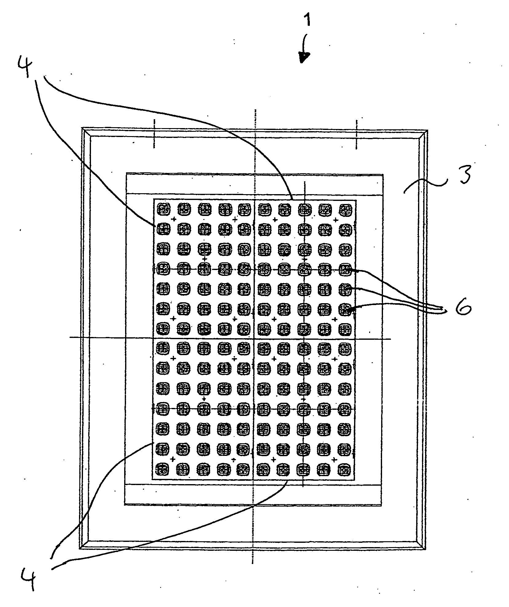
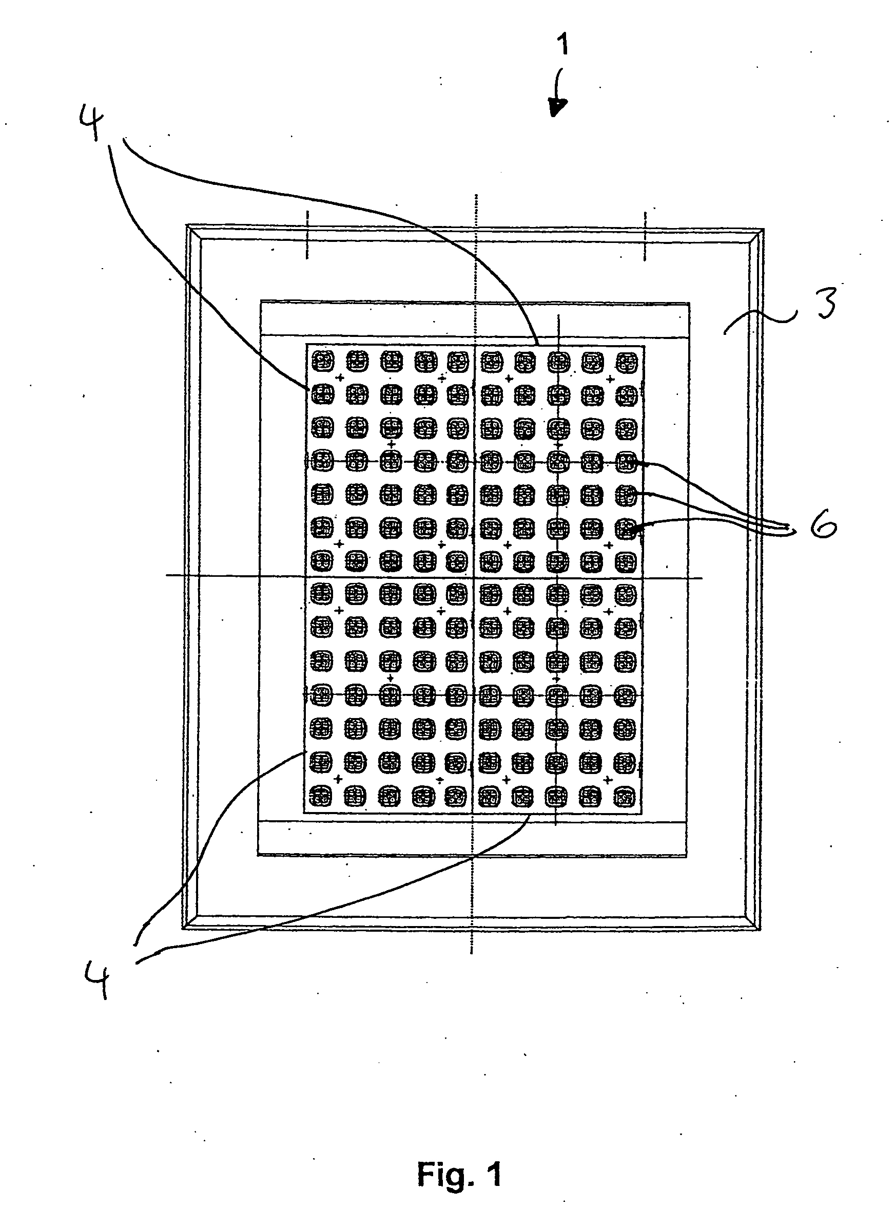
[0025]FIG. 1 shows a modular display device 1 having a supporting frame 3 and display modules 4 inserted into this supporting frame 3. In the embodiment shown, four display modules 4 are assembled to form a rectangular display field. However, any number of display modules 4 can be strung together. Each display module 4 has a rectangular display field, in which thirty-five signal fields are arranged in five columns and seven lines. Of course, a variation of the number and distribution of the signal fields 6 in the individual display modules 4 is also possible. Display device 1 may be attached via the supporting frame 3 to a supporting device (not shown), such as a pole, a signboard supporting bridge structure or another suitable equivalent for carrying display device 1.

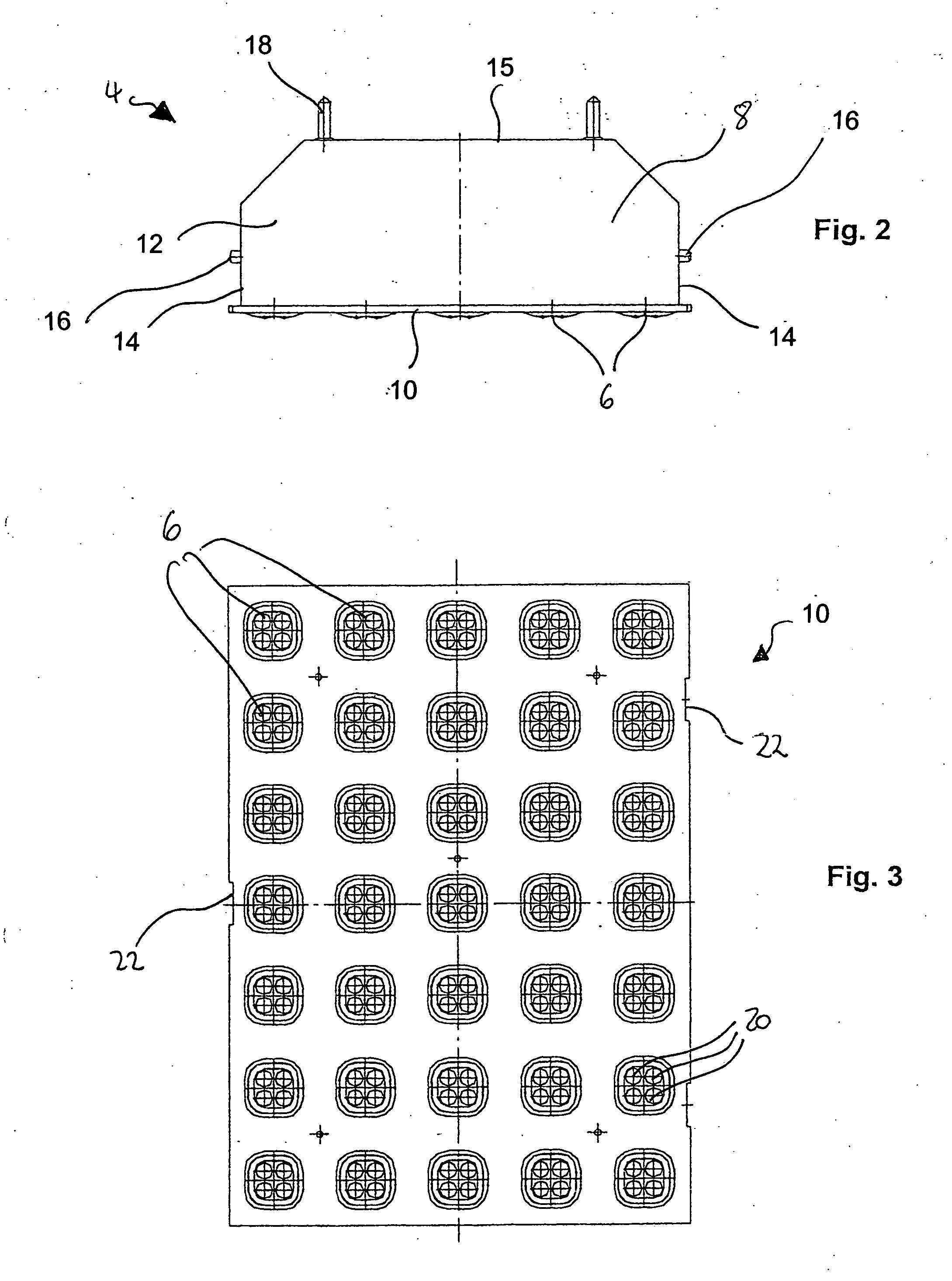
[0026]FIG. 2 shows a preferred embodiment of a display module 4. The display module 4 has a module housing 8 that includes a front plate 10 with integrated signal fields 6 as well as a rear base body 12 with four side...


PUM


Abstract

A modular display device for optical signals includes a supporting frame and a plurality of display modules each having a module housing and a plurality of light emitting diodes integrated therein. The module housings are inserted into the supporting frame and are releasably attached thereto. The attachment of the module housings in the supporting frame is implemented by movable snap-in locking members that are structured for engaging respective holding elements disposed on at least two opposing side walls of each module housing. The snap-in locking members of adjacent side walls of different module housings are arranged to be offset with respect to each other.

Description

FIELD OF THE INVENTION [0001] The present invention refers to a modular display unit for optical signals and to a tool for removing display modules from a supporting frame of a modular display device. BACKGROUND OF THE INVENTION [0002] A display device is described in DE 199 51 348 A1, incorporated herein by reference. Such display device includes a display field formed of several identical display modules, wherein the pixels are arranged line-wise and column-wise and are controlled by a controller. The attachment of the individual module housings to the supporting structure is implemented by screwing an angular holder, which engages at the front side of the module housing, to the supporting structure. One disadvantage of such an attachment is particularly that the individual module housings cannot be arranged directly adjacent to each other and, therefore, a uniform display field, which is also suitable for all types of module-overlapping signal displays, is not created. Secondly, ...

Claims


Application Information

Patent Timeline
IPC IPC(8): B25B27/02B25B27/30G09F9/00G09F9/33G09G3/20G09G3/22G09G5/00
CPCG09F9/3026G09F9/33
Inventor BAUMSTARK, ERWIN
Owner DAMBACH WERKE
Why Eureka
Try Eureka