Filtering device for vacuum cleaner

a filtering device and vacuum cleaner technology, applied in the field of vacuum cleaners, can solve the problems of deteriorating suction force, difficult discharge, and filter cleaning or replacement periodicity

Inactive Publication Date: 2005-10-06
LG ELECTRONICS INC
View PDF4 Cites 30 Cited by
  • Summary
  • Abstract
  • Description
  • Claims
  • Application Information

AI Technical Summary

Benefits of technology

[0017] Therefore, an object of the present invention is to provide a filtering device for a vacuum cleaner capable of preventing a channel of a filter from being closed with dust, by self-removing fine dust attached to a filter in a cleaning operation.

Problems solved by technology

However, the above-mentioned conventional vacuum cleaner has disadvantages in that the filter has to be cleaned or replaced periodically.
This is because when the conventional vacuum cleaner is used for a certain period of time, fine dust is attached to the filter of the filtering device, thereby deteriorating a suction force.
That is, since fine dust fills up a close mesh of the filter, it is difficult to discharge air, which is sucked through the suction opening, through the filter, and finally a decrease in suction force is caused.
Accordingly, if the filter is not cleaned or replaced periodically, cleaning cannot be effectively performed due to the deterioration of the suction force.

Method used


Image

  • Filtering device for vacuum cleaner
  • Filtering device for vacuum cleaner
  • Filtering device for vacuum cleaner

Examples


Embodiment Construction

[0033] Reference will now be made in detail to the preferred embodiments of the present invention, examples of which are illustrated in the accompanying drawings.

[0034] There may exist a plurality of embodiments of a filtering device for a vacuum cleaner in accordance with the present invention, and hereinafter, the most preferred embodiment will be described.

[0035] In addition, the same reference numerals will be given to the same components as the conventional art.

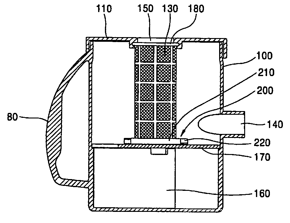
[0036]FIG. 5 is a disassembled perspective view of a filtering device for a vacuum cleaner in accordance with the present invention, FIG. 6 is a longitudinal sectional view taken along line VI-VI of FIG. 5 and showing an assembled filtering device in accordance with the present invention, and FIG. 7 is a perspective view of a filter cleaning unit in accordance with the present invention.

[0037] As shown therein, a filtering device of a vacuum cleaner in accordance with the present invention is provided with a knob 80 ...


PUM


Abstract

A filtering device for a vacuum cleaner comprises: a casing having a collecting space therein, a suction opening through which air including dust is sucked and a discharge opening through which purified air is discharged; a filter installed at the internal space of the casing, for filtering dust from air sucked through the suction opening; and a filter cleaning unit disposed to encompass an outer circumferential surface of the filter, for cleaning the filter by being rotated by a rotation force of air sucked through the suction opening. Accordingly, the filtering device can remove fine dust attached to the filter in a cleaning operation, thereby preventing a channel of the filter from being closed with the dust.

Description

BACKGROUND OF THE INVENTION [0001] 1. Field of the Invention [0002] The present invention relates to a vacuum cleaner, and more particularly, to a filtering device for a vacuum cleaner capable of removing dust attached to a filter in operation of a cleaner. [0003] 2. Description of the Background Art [0004] In general, a vacuum cleaner is an electronic device for cleaning an indoor space such as a room, an office or the inside of a car. Undesired impurities such as dust, which exists at home or in a car can be removed by using a suction force of the vacuum cleaner. [0005]FIG. 1 is a perspective view showing a structure of a general vacuum cleaner. [0006] As shown therein, a general vacuum cleaner includes a cleaner main body 1 and a suction head 2 connected to the cleaner main body 1 by a suction hose 3 and an extension pipe 4, to which dust and foreign substances are sucked from a floor. [0007] The cleaner main body 1 includes a suction force generating part (not shown) for generat...

Claims


Application Information

Patent Timeline
Patent Type & Authority Applications(United States)
IPC IPC(8): A47L9/10A47L9/20
CPCA47L9/20A47L9/10
Inventor REW, HO-SEONCHUNG, CHOON-MYUN
Owner LG ELECTRONICS INC
Why Eureka
Try Eureka