LED lighting device and system

a technology of led lighting and lighting tubes, which is applied in the direction of mass transit vehicle lighting, lighting support devices, landing aids, etc., can solve the problems of short life of flourescent lighting tubes, high power requirements, and disadvantages for customers

Inactive Publication Date: 2005-03-29
HEADS UP TECH
View PDF20 Cites 174 Cited by
  • Summary
  • Abstract
  • Description
  • Claims
  • Application Information

AI Technical Summary

Problems solved by technology

However, flourescent lights possess many characteristics which are disadvantageous to the customer.
The disadvantages include the short lifetime of the flourescent lighting tube, high power requirements, low durability, high cost for specialty designs, and high electromagnetic interference which can be detrimental to other electrical systems.
However, this system is not directed toward a high power LED lighting system.
Namely, this system, which encloses the LEDs in a sealed plastic tube, does not disclose the need for heat dissipation when high power and high heat LEDs are used.
However, this system does not address dissipating the high heat generated when a lighting system uses LEDs in close proximity with each other.
However, this system does not address the needs of a replaceable, movable, and durable lighting system for use to light the interior cabin of vehicles.

Method used


Image

  • LED lighting device and system
  • LED lighting device and system
  • LED lighting device and system

Examples


Embodiment Construction

In the description that follows, like parts are marked throughout the specification and drawings with the same reference numerals, respectively. The drawing figures are not necessarily drawn to scale and certain figures may be shown in an exaggerated or generalized form in interest of clarity and conciseness.

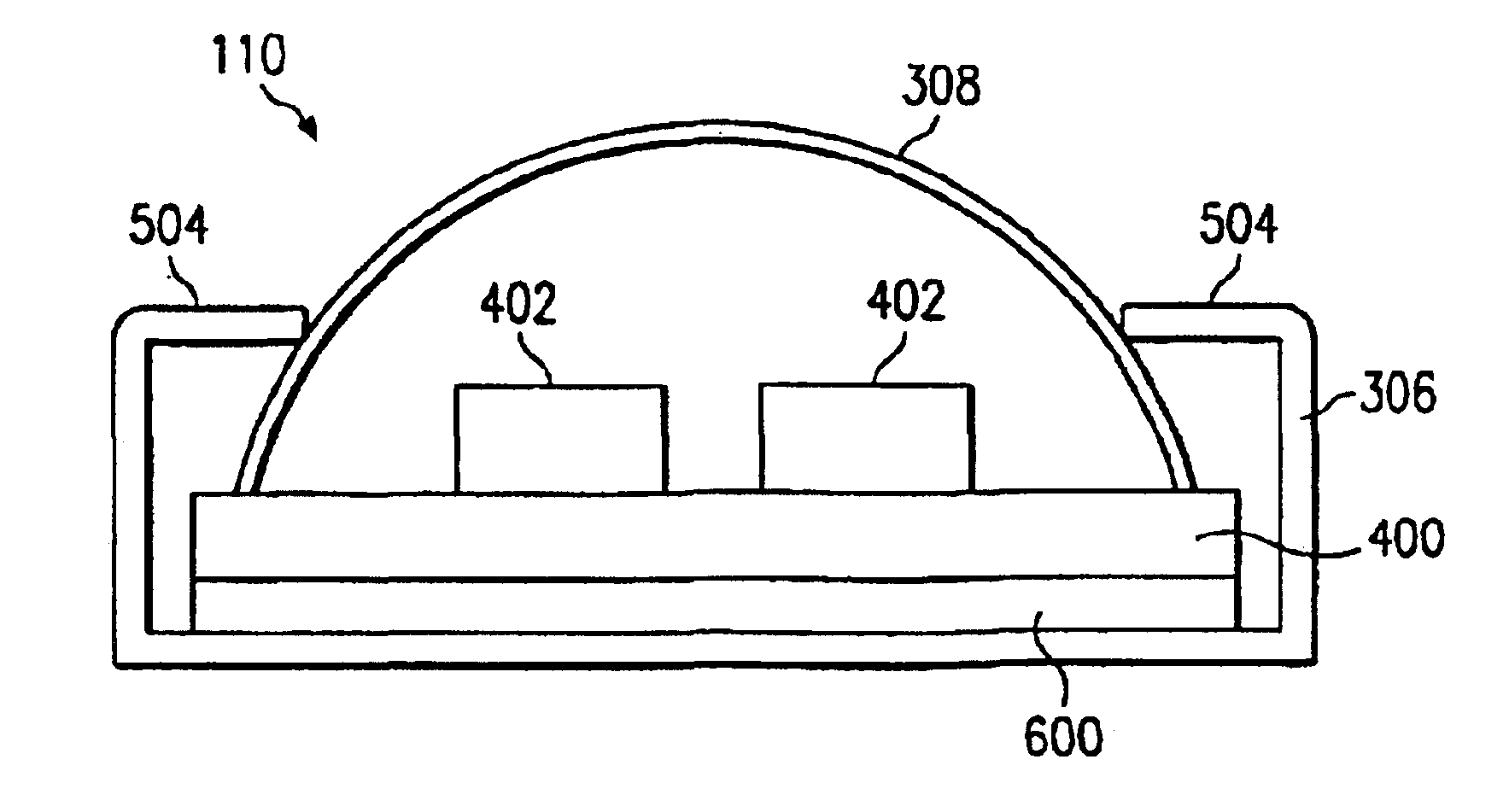
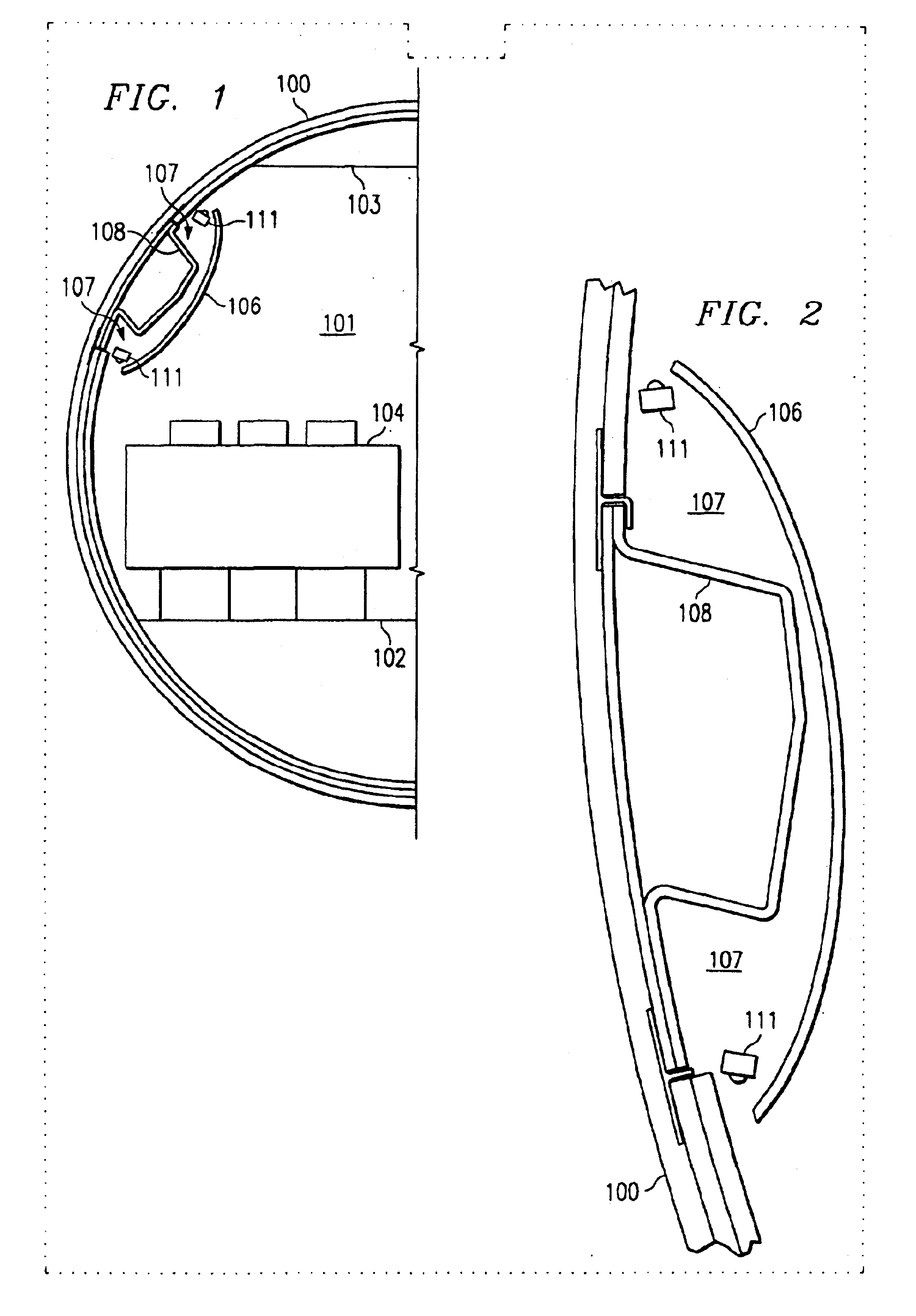
FIGS. 1 and 2 illustrate a cross-sectional view of the cabin of an airplane including the LED lighting system according to the present invention. The aircraft fuselage 100 is shown. The aircraft fuselage 100 includes an aircraft cabin 101. The aircraft cabin 101 is defined by an artificial ceiling 103 and an artificial floor 102. Seats 104 are attached to the artificial floor 102. A lighting and duct panel 106 is provided above seats 104. A duct 108 is shown attached to the aircraft fuselage 100 and is positioned behind the lighting and duct panel 106. The lighting and duct panel 106, the duct 108 and the aircraft fuselage 100 form a cavity 107. Within cavity 107, the LED lighti...


PUM


Abstract

A lighting device and system for illuminating the interior of a vehicle, aircraft or building is provided. The lighting device and system includes a channel case made from a thermally conductive material, including aluminum. The channel case has a bottom edge and two opposed side edges forming an interior space. A circuit board is disposed within the interior space of the channel case and the circuit board includes circuit traces on the top, bottom or both sides of the circuit board. A heat transfer device is attached to the bottom of the circuit board and is further attached to the bottom of the channel case. A plurality of light-emitting diodes and resistors are mounted on the circuit board in series and generate light through a lens which is attached to the two opposed side edges of the channel case.

Description

CROSS-REFERENCE TO RELATED APPLICATIONSNot Applicable.STATEMENT REGARDING FEDERALLY SPONSORED RESEARCH / DEVELOPMENTNot ApplicableFIELD OF THE INVENTIONThe field of the invention relates to an alternative lighting device and system for use in a vehicle, building or aircraft and, more specifically, a lighting device and system for illuminating the interior space of a vehicle, building or aircraft using white light emitting diodes (LEDs).BACKGROUND OF THE INVENTIONFor many years the lighting of the interiors of automobiles, aircraft, trains and other vehicles has been accomplished with the use of flourescent lighting systems. Flourescent lights, otherwise known as cold cathode lights, were widely used in direct or indirect lighting systems. However, flourescent lights possess many characteristics which are disadvantageous to the customer. The disadvantages include the short lifetime of the flourescent lighting tube, high power requirements, low durability, high cost for specialty design...

Claims


Application Information

Patent Timeline
Patent Type & Authority Patents(United States)
IPC IPC(8): B60Q3/02B60Q3/00F21V29/00
CPCB60Q3/025B60Q3/0259F21V29/763F21V29/004F21S48/328B60Q2500/20F21Y2101/02B60Q3/43B60Q3/47F21Y2115/10F21S43/15F21S45/47F21W2107/30Y10S362/80F21V29/74
Inventor ALEXANDERSON, JAMES KENNETHHARSHAW, ROBERT C.
Owner HEADS UP TECH
Why Eureka
Try Eureka