
Field steerable electrical stimulation paddle, lead system, and medical device incorporating the same

a technology of lead system and electric stimulation paddle, which is applied in the field of medical devices, can solve the problems of difficult to properly position the spinal cord, need to be repositioned, and procedure that carries risks, and requires great patience, care and skill

Inactive Publication Date: 2005-03-31
MEDTRONIC INC
View PDF44 Cites 207 Cited by
  • Summary
  • Abstract
  • Description
  • Claims
  • Application Information

AI Technical Summary

Benefits of technology

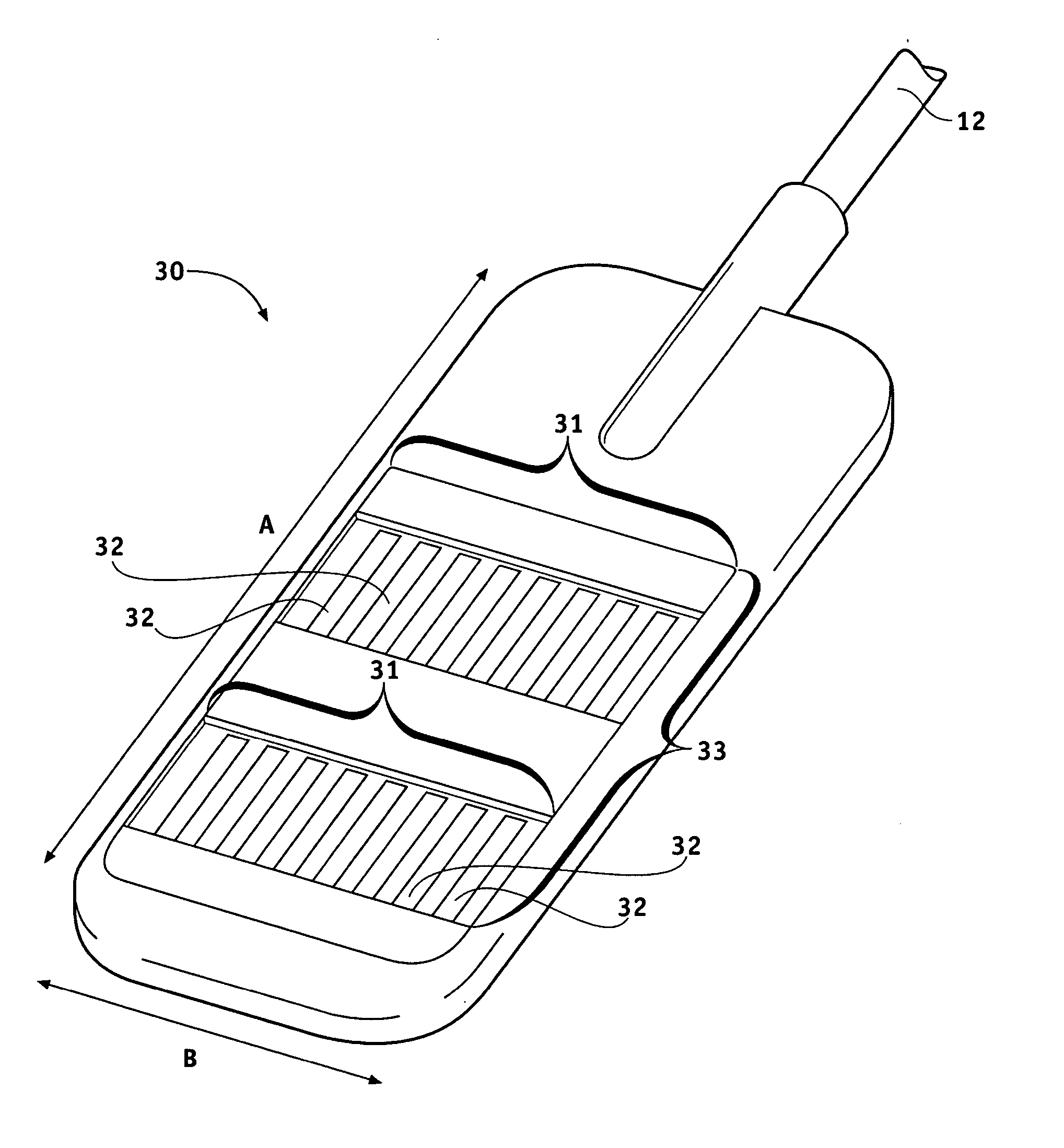
The patent describes an implantable electrode paddle that can be used to stimulate body tissue by receiving an electrical signal from a medical device and generating an electrical field. The electrode paddle has a housing with windows for transmitting the electrical field to the tissue. The paddle also has an electrode array with multiple electrode groups, each containing at least two electrodes, which are secured in the windows. The electrodes are spaced between 0.1 mm and 10 mm apart. The system also includes a lead body and an implantable medical device with a controlling device for generating the electrical field. The method for manufacturing the electrode paddle involves assembling the electrode array onto a substrate with windows for transmitting the electrical field to the tissue. The technical effects of this invention include improved stimulation of body tissue with a more targeted and efficient electrical field, and reduced risk of complications from the implantation process.

Problems solved by technology

However, physicians have found that it can be difficult to properly position the spinal cord stimulation lead to achieve good pain relief for lower back pain.
Even if the technique is performed properly, the leads may need to be repositioned over time.
Repositioning the stimulating leads is typically an invasive surgical procedure that carries risks and requires great patience, care, and skill.

Method used


Image

  • Field steerable electrical stimulation paddle, lead system, and medical device incorporating the same
  • Field steerable electrical stimulation paddle, lead system, and medical device incorporating the same
  • Field steerable electrical stimulation paddle, lead system, and medical device incorporating the same

Examples


Embodiment Construction

[0020] The following detailed description is merely exemplary in nature and is not intended to limit the invention or the application and uses of the invention. Furthermore, there is no intention to be bound by any expressed or implied theory presented in the preceding technical field, background, brief summary or the following detailed description.

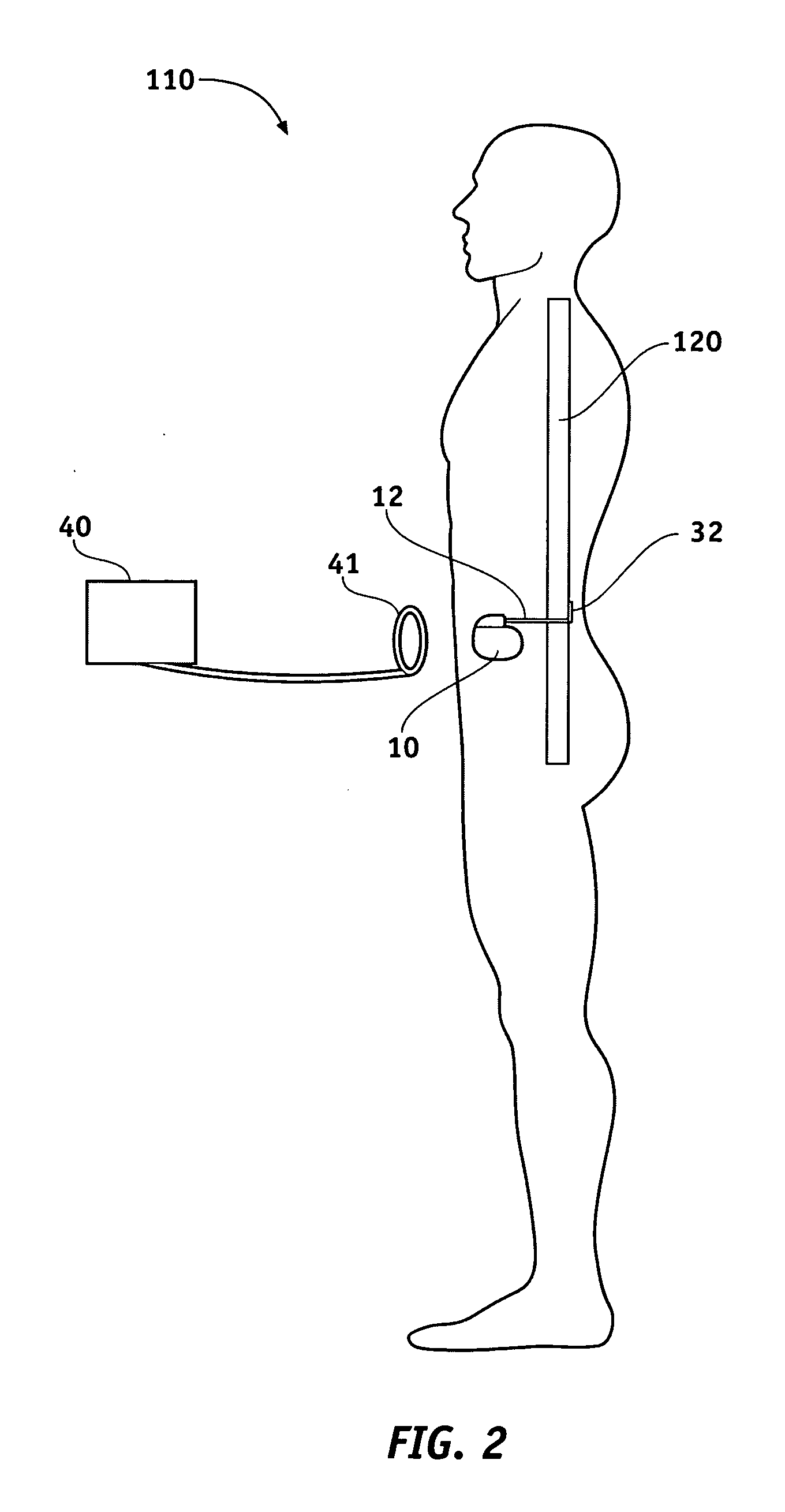
[0021] While the following description is generally directed to treatments and systems involving a neurological stimulator in the form of an implantable pulse generator, the utility of the apparatus and method of the present invention is not limited to neurostimulatory pulse generating devices and can be adapted for use with a variety of implantable electrical devices that use multiple electrical leads to send electrical pulses to selected body parts. FIG. 2 is an illustration of a patient 110 with an implantable pulse generator (IPG) 10 implanted in the patient's abdomen. The IPG 10 transmits independent stimulation pulses to the spinal...


PUM

PropertyMeasurementUnit
sizesaaaaaaaaaa
electrical fieldaaaaaaaaaa
electricalaaaaaaaaaa

Abstract

An implantable electrode paddle is adapted to receive an electrical signal from a medical device and generate an electrical field to stimulate selected body tissue. The paddle includes a housing including walls that define an interior space and a plurality of windows formed through at least a first one of the walls for transmitting the electrical field to the body tissue, an electrode array including a plurality of electrode groups, each electrode group including at least two electrodes individually secured in a respective window and spaced between about 0.1 mm and about 10 mm apart, and a plurality of wires, each of the wires being coupled to a respective electrode and routed within the interior space to receive the electrical signal. A lead assembly and an implantable medical device can include the paddle.

Description

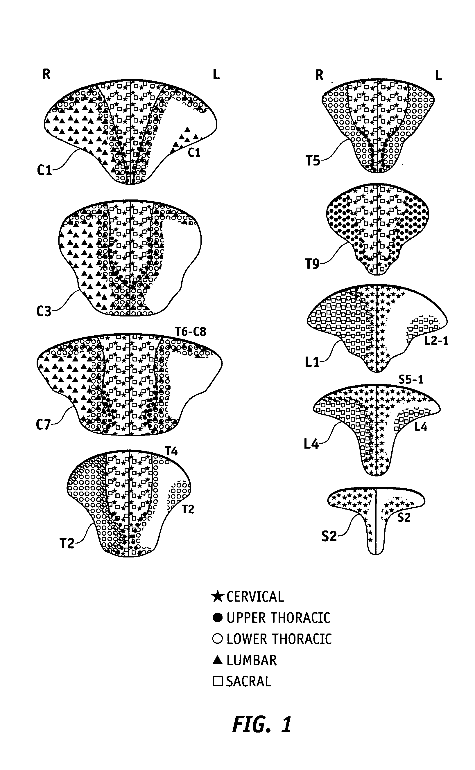
[0001] This application claims the benefit of U.S. Provisional Application No. 60 / 507,832, filed Oct. 1, 2003, and 60 / 507,389, filed Sep. 30, 2003 which are hereby incorporated herein by reference in their entirety.TECHNICAL FIELD [0002] The present invention generally relates to medical leads for biological tissue therapy, and more particularly relates to systems and methods for steering a tissue stimulating electrical field using implantable medical leads. BACKGROUND [0003] Dorsal columns are long myelinated fibers oriented along the spinal cord axis and centrally located around the lumbar spine between the dorsal roots. Researchers have found that fibers enter the dorsal horn, and are arranged in approximately v-shaped layers. Fibers that enter at a higher vertebral level form a v-shaped layer covering the layers that originated at lower levels. The nerve fiber organization is less structured below the dorsal column surface, where the fibers are two or more vertebral levels away ...

Claims


Application Information

Patent Timeline
Patent Type & Authority Applications(United States)
IPC IPC(8): A61N1/05A61N1/34
CPCA61N1/0553Y10T29/49204A61N1/36071
Inventor HERUTH, KENNETH T.HOLLE, MARKSKAKOON, JAMES
Owner MEDTRONIC INC
Learn More