Flow regulators with flexible diaphragms

Inactive Publication Date: 2005-10-13
NAANDAN JAIN IRRIGATION C S
View PDF10 Cites 39 Cited by
  • Summary
  • Abstract
  • Description
  • Claims
  • Application Information

AI Technical Summary

Benefits of technology

[0025] There is also provided according to the teachings of the present invention, a flow regulator for regulating a rate of flow of a liquid from an inlet flow path to an outlet flow path, the flow regulator comprising: (a) a housing including at least one wall which defines, at least in part, a regulation chamber having a substantially annular surface and an outlet aperture in fluid communication with the outlet flow path; and (b) a flexible diaphragm deployed at least partially within the regulation chamber, the diaphragm having a first surface part of which faces towards the substantially annular surface and a second surface part of which faces towards the outlet aperture, the diaphragm assuming an initial unflexed position in which part of the first surface lies substantially adjacent to the substantially annular surface, the diaphragm being displaceable under pressure applied from the inlet flow path to a fle

Problems solved by technology

In most cases, the diaphragm tends to oscillate rapidly during operation.
Notwithstanding these advantages, the structures of diaphragm-based flow regulating devices proposed to-date suffer from a number of limitations.
Most notably, the oscillation of the diaphragm causes repeated impact of the central portion of the diaphragm against the surfaces surrounding the outlet aperture, thereby reducing the lifetime of the device.
Any non-uniformity in the elastic properties of the diaphragm, or misalignment of the diaphr

Method used


Image

  • Flow regulators with flexible diaphragms
  • Flow regulators with flexible diaphragms
  • Flow regulators with flexible diaphragms

Examples


Embodiment Construction

[0043] The present invention is a flow regulator employing a flexible diaphragm with a thickened contact portion.

[0044] The principles and operation of flow regulators according to the present invention may be better understood with reference to the drawings and the accompanying description.

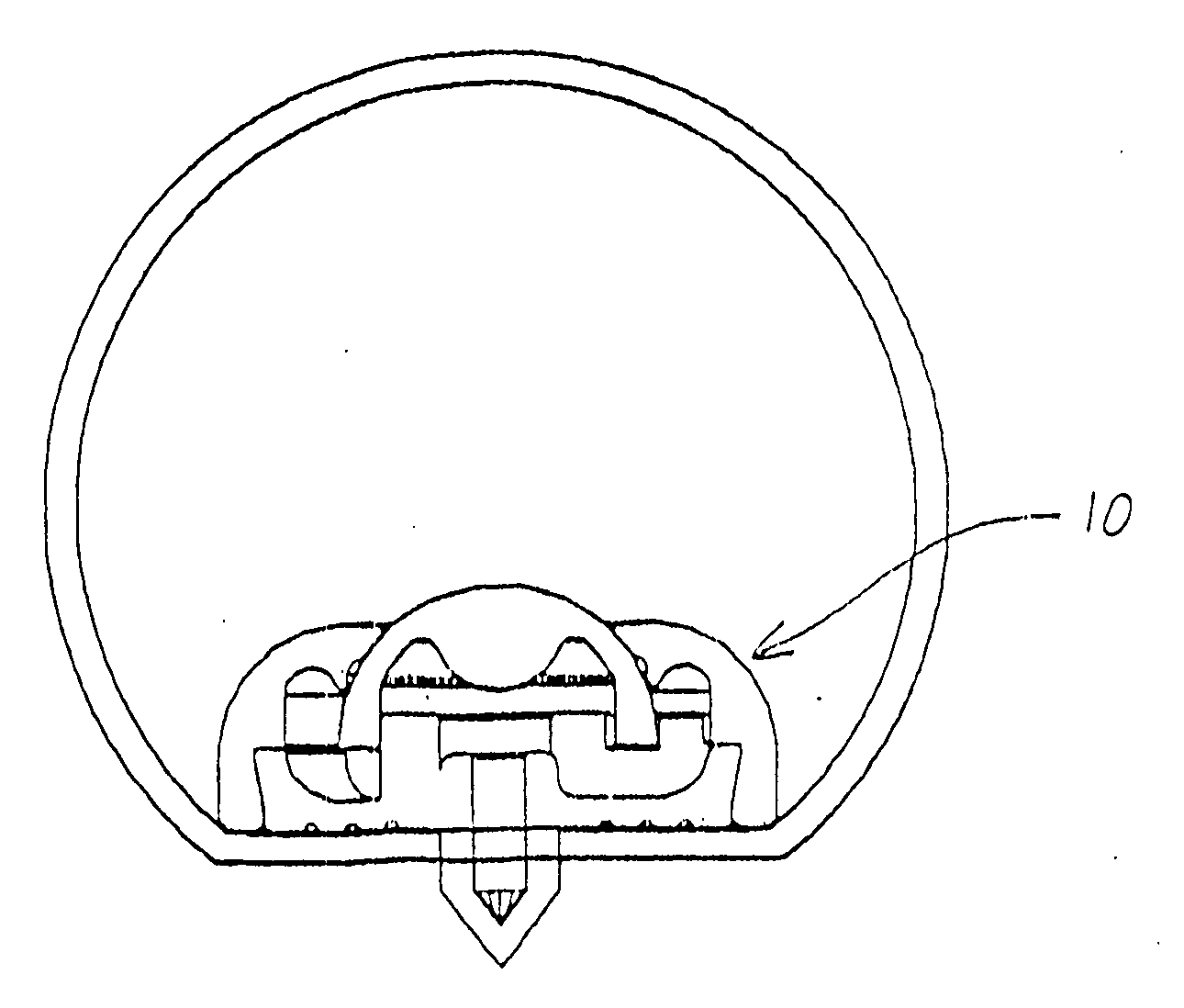
[0045] Referring now to the drawings, FIGS. 4 and 5 show a first embodiment of a flow regulator, generally designated 10, constructed and operative according to the teachings of the present invention, for regulating a rate of flow of a liquid from an inlet flow path to an outlet flow path. In this embodiment, regulator 10 is a drip emitter for mounting internally within a drip irrigation tube (not shown) such that the “inlet flow path” encompasses the entire upper surface of the regulator as shown, and the “outlet flow path” opens directly to the outside of the tube through a release conduit 12.

[0046] In general terms, regulator 10 has a housing 14 including at least one wall which defines, at...


PUM


Abstract

A flow regulator (10) for regulating a rate of flow of a liquid from an inlet flow path to an outlet flow path. The flow regulator includes a housing (14) with one wall or more which defines, at least in part, a regulation chamber (16) with all annular surface (18) and an outlet aperture (20) in fluid communication with the outlet flow path. The flow regulator also includes a flexible diaphragm (22) deployed at least partially within the regulation chamber (16), the diaphragm (22) having a first surface (24) part of which faces towards the annular surface (18) and a second surface (26) part of which face towards the outlet aperture (20), the diaphragm (22) assuming an initial unflexed position in which part of the first surface (24) lies adjacent to the annular surface (18), the diaphragm (22) is displaceable under pressure applied from the inlet flow path to a flexed position in which the first surface (24) is at least partially removed from the annular surface (18) and a contact portion of the second surface (26) obstructs the outlet aperture (20).

Description

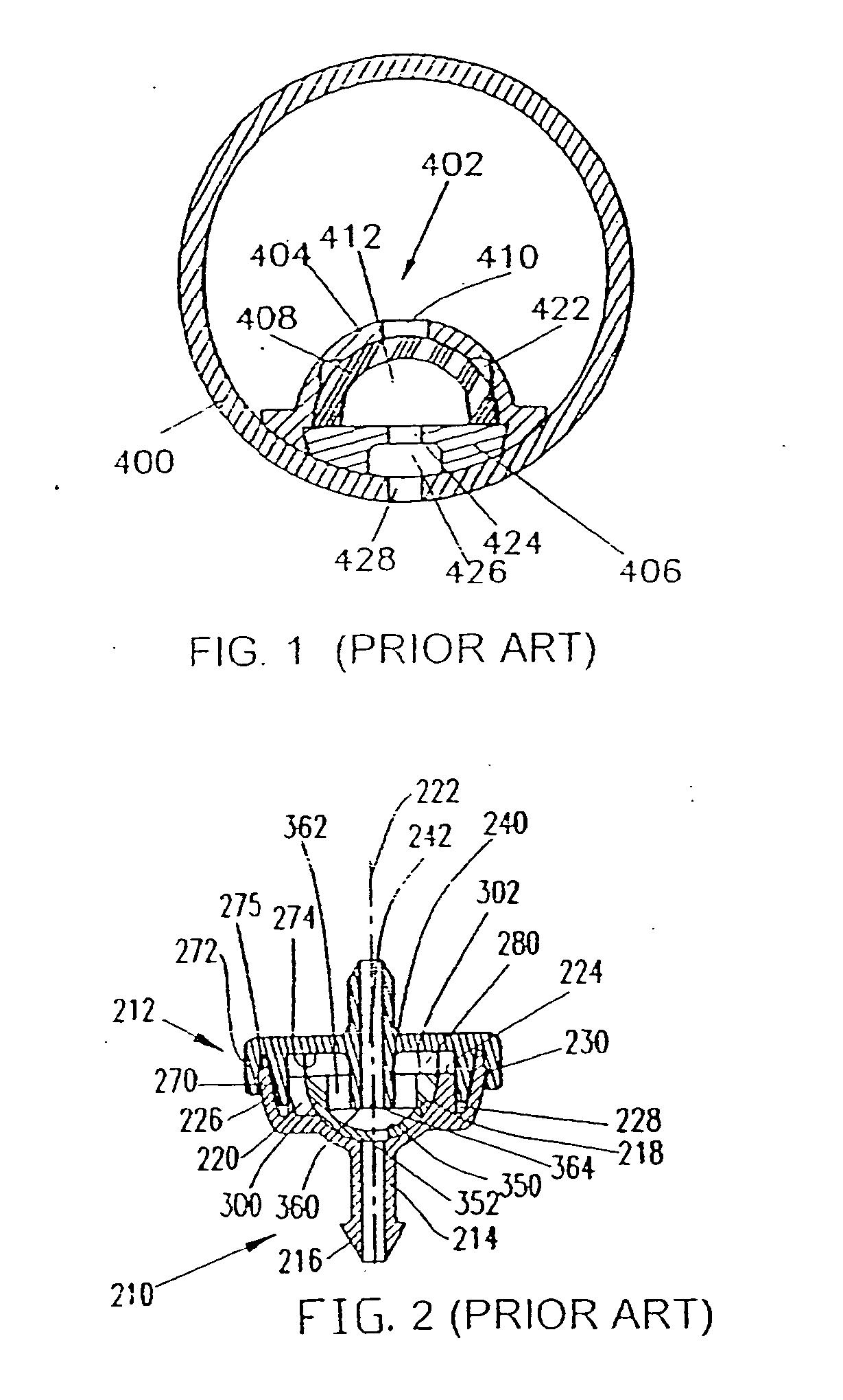
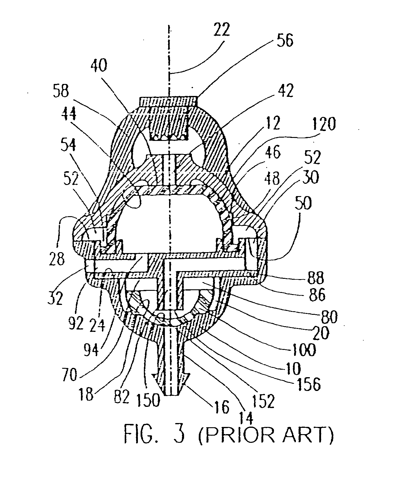
FIELD AND BACKGROUND OF THE INVENTION [0001] The present invention relates to irrigation devices and, in particular, it concerns flow regulators employing flexible diaphragms. [0002] It is known to employ a flexible diaphragm to provide pressure-sensitive flow control in irrigation devices. A number of such devices are described in U.S. Pat. No. 5,820,028 to the present applicant which is hereby incorporated in its entirety. [0003] By way of example, FIGS. 1-3 show three devices, corresponding to FIGS. 6A, 4A and 3A, respectively, from the aforementioned patent. Specifically, FIG. 1 shows a drip-irrigation emitter mounted on the inner surface of a drip-irrigation tube, FIG. 2 shows a self-contained emitter unit, and FIG. 3 shows a pulsator device. In each case, water flow is regulated by movement of a dome-shaped flexible diaphragm, part of which becomes inverted by application of a supply pressure to vary an outlet geometry defined by an outlet aperture and an inner surface of the ...

Claims


Application Information

Patent Timeline
IPC IPC(8): G05D7/01
CPCG05D7/0113
Inventor DINUR, ELDADGORNY, MOSHE
Owner NAANDAN JAIN IRRIGATION C S
Why Eureka
Try Eureka