Door stop

Inactive Publication Date: 2005-10-20
BARONE NEIL
View PDF22 Cites 15 Cited by
  • Summary
  • Abstract
  • Description
  • Claims
  • Application Information

AI Technical Summary

Benefits of technology

[0002] An object of this invention is to provide a doorstop which would be mounted directly on the door in a simple and convenient manner without requiring tools for its installation.
[0004] In accordance with this invention the door stop is in the form of a generally U-shaped base having a pair of upwardly extending vertical walls interconnected by a bottom wall. The base could be mounted to the bottom edge of the door by simply being inserted around the bottom edge. A spacing member extends outwardly from one of the vertical walls of the base toward the room wall. One end of the spacing member is secured to one of the vertical walls of the base while the free end would be disposed remote from that vertical wall and toward the room wall during the swinging action. A contact tip is provided at the free end to contact the room wall or molding without causing damage. The length of the spacing member is greater than the length or extension of the door hardware, such as the doorknobs so that when the contact tip reaches the room wall the door hardware is spaced from and out of contact with the room wall thereby avoiding any damage.

Problems solved by technology

A problem exists when the hardware, such as the doorknob, would be pushed into contact with the wall of the room, which could result in damage to the room wall.
The various traditional doorstops are difficult to install, require tools, such as scewdrivers, wrenches and even power drills and still often result in damage to the walls or doors when they are installed by the making of screw holes.
In addition, particularly when there is faulty installation the doorstops fall off after continued use.

Method used


Image

  • Door stop
  • Door stop

Examples


Embodiment Construction

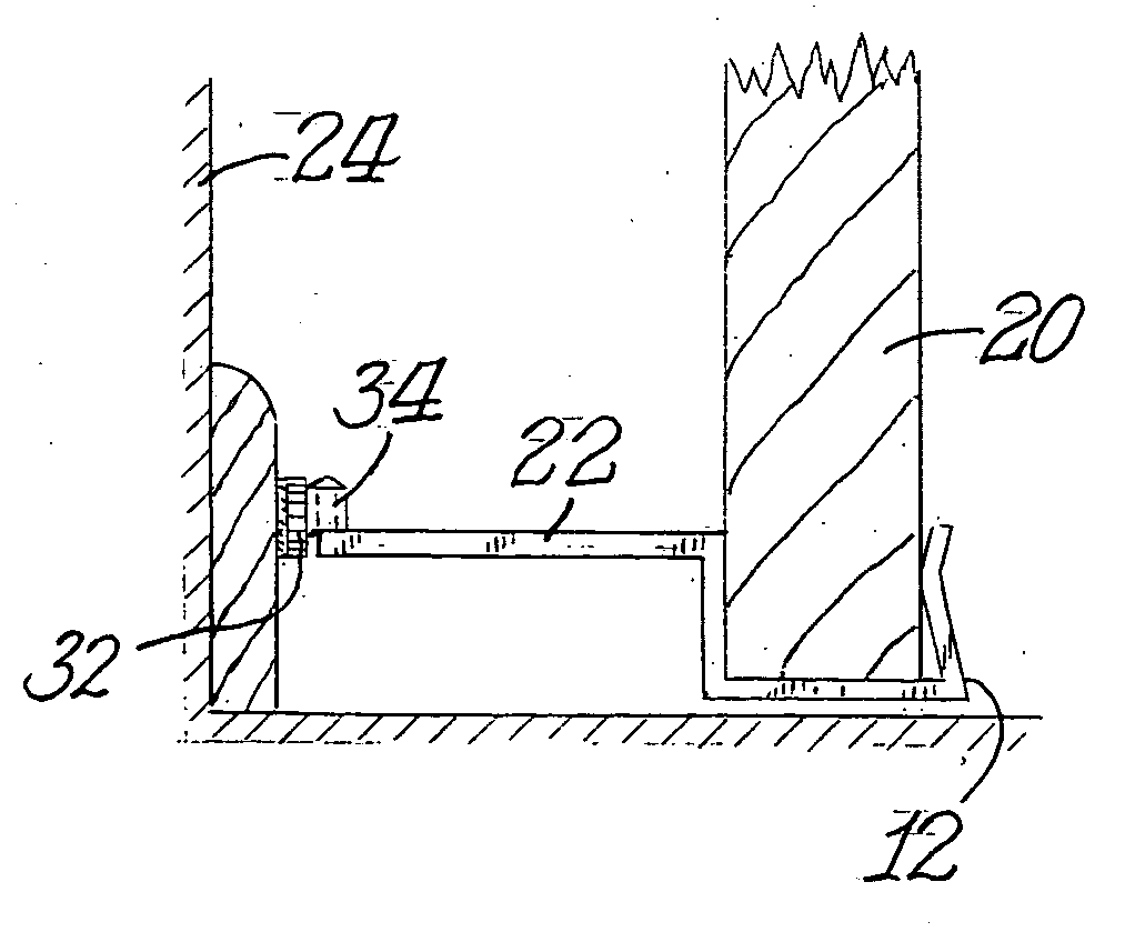
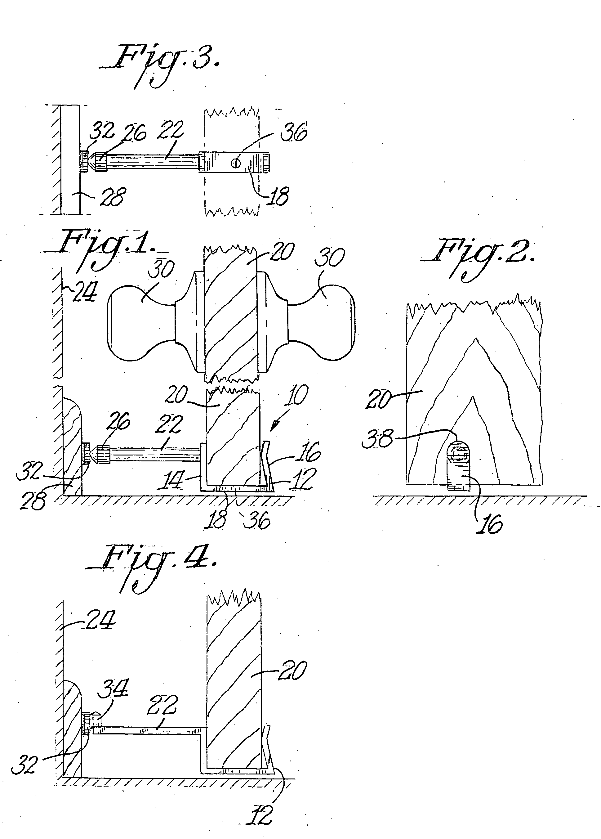
[0011] As shown in FIGS. 1-3 the door stop 10 includes a base 12 which is generally U-shaped. Base 12 has a pair of upwardly extending vertical walls 14,16 interconnected by a bottom wall 18. Preferably, at least one of the walls, such as wall 16, is made of a resilient material and is bowed inwardly toward the other wall 14 so that the distance between the two walls at the bowed in portion is less than the thickness of the door 20. Otherwise the spacing between walls 14 and 16 would preferably be at least slightly greater than the thickness of door 20. As a result, door stop 10 could be easily installed on door 20 by simply sliding the U-shaped base 12 along-the bottom of door 20 as illustrated in FIGS. 1 and 4.

[0012] Door stop 10 further includes a spacing member 22 which extends outwardly from vertical wall 14. One end of spacing member 22 is mounted to vertical wall 14 in any suitable manner. FIG. 1, for example, shows the anchored end to be welded to wall 14. FIG. 4 illustrate...


PUM


Abstract

A door stop is in the form of a generally U-shaped base having a spacing member extending outwardly from one of the vertical walls of the base. The door stop is slidably mounted on the bottom of a door. The spacing member is of a length greater than the distance a doorknob or other door hardware extends from the door. As a result, when the door is swung to its open position the spacing member contacts the room wall to prevent the door hardware from contacting the room wall. A magnet could be mounted to the wall molding to magnetically hold the door in its open position where at least part of the door stop is made of metal.

Description

BACKGROUND OF THE INVENTION [0001] Most household doors and doors in buildings and offices are swingably mounted on hinges along one vertical end of the door. Commonly, such doors include various types of door hardware, such as doorknobs, which extend outwardly from the sides of the door. A problem exists when the hardware, such as the doorknob, would be pushed into contact with the wall of the room, which could result in damage to the room wall. Various techniques have been used in order to limit the extent that a door could be swung open, particularly, various types of door stops have been used. A traditional approach is to mount a door stop in the wall of a room extending outwardly a sufficient amount so that it is contacted by the swinging door before the doorknob or other hardware makes contact with the room wall. Such door stops are generally screwed or otherwise fastened to the wall or wall molding. Another approach is to mount a doorstop on a hinge of the door to limit the e...

Claims


Application Information

Patent Timeline
IPC IPC(8): E05C17/56E05F5/02E05F5/06
CPCE05C17/56Y10T16/61E05F5/06
Inventor BARONE, NEIL
Owner BARONE NEIL
Why Eureka
Try Eureka