Methods of servicing a well bore using self-activating downhole tool

a self-activating, well-bore technology, applied in the direction of borehole/well accessories, fluid removal, survey, etc., can solve the problems of increased safety concerns, time-consuming and costly operations, mechanical connection,

Active Publication Date: 2005-11-03
HALLIBURTON ENERGY SERVICES INC
View PDF53 Cites 207 Cited by
  • Summary
  • Abstract
  • Description
  • Claims
  • Application Information

AI Technical Summary

Benefits of technology

[0011] The method may further comprise deploying into the well bore a second zonal isolation device operable to self-set at a second sensed location above the set of perforations, and self-setting the second device to seal the well bore at the second sensed location. In an embodiment, the second device is operable to identify the second sensed location without receiving communications from the surface. In an embodiment, the method further comprises deploying a second perforating gun into the well bore after the second device is set, and firing the gun to form another set of perforations in the well bore. In an embodiment, the second perforating gun is deployed by dropping the gun down the well bore via gravity, pumping the gun down the well bore, or a combination thereof. In an embodiment, deployment of the second gun is stopped when a second spacing component engages both the second set device and the second perforating gun. In an embodiment, the method further comprises at least partially collapsing, folding, bending, buckling, fragmenting, dissolving, burning away, or combinations thereof the second spacing component during or after firing the second gun to lower the second gun with respect to the another set of perforations. In an embodiment, the method further comprises deploying a perforating gun within the well bore before the device is deployed, and firing the gun to form at least the set of perforations. In an embodiment, the perforating gun is deployed by dropping the gun down the well bore via gravity, by pumping the gun down the well bore, or a combination thereof. In an embodiment, the perforating gun is operable to self-fire at one or more sensed locations. In an embodiment, the perforating gun is operable to identify the one or more sensed locations without receiving communications from the surface.
[0012] In an embodiment, the method further comprises releasing the device to unseal the well bore. In an embodiment, the device self-releases without receiving communications from the surface. In an embodiment, the method further comprises returning the device to the surface by floating the device to the surface, flowing the device to the surface, or both. In an embodiment, releasing the device comprises at least partially degrading the device within the well bore. In an embodiment, the method further comprises retrieving the device via a connection to the surface. In an embodiment, the method further comprises fishing the device out of the well bore. In an embodiment, the method further comprises self-setting the device at a desired azimuth orientation. In an embodiment, the method further comprises azimuthally orienting the perforating gun with respect to the set device.
[0013] Further disclosed herein is a method of servicing a well bore comprising deploying into the well bore a tool operable to self-activate at one or more locations, and self-navigating the tool to determine the one or more locations without receiving communications from the surface, wherein the tool is moved along at least a partial length of the well bore via an external force. In various embodiments, servicing a well bore comprises servicing a deviated well bore, servicing a lateral well bore, drilling a lateral well bore, or abandoning the well bore.

Problems solved by technology

This mechanical connection may be subject to various problems including time consuming and costly operations, increased safety concerns, more personnel on site, and risk for breakage of the connection.

Method used


Image

  • Methods of servicing a well bore using self-activating downhole tool
  • Methods of servicing a well bore using self-activating downhole tool
  • Methods of servicing a well bore using self-activating downhole tool

Examples


Embodiment Construction

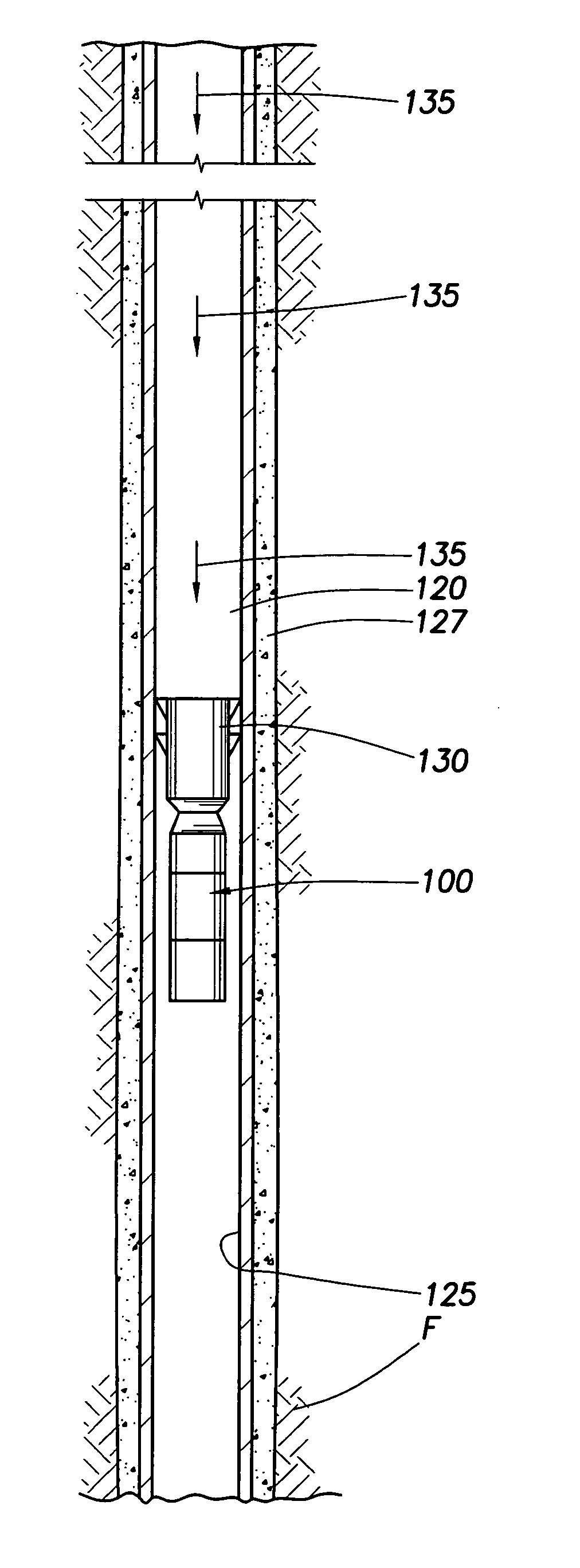
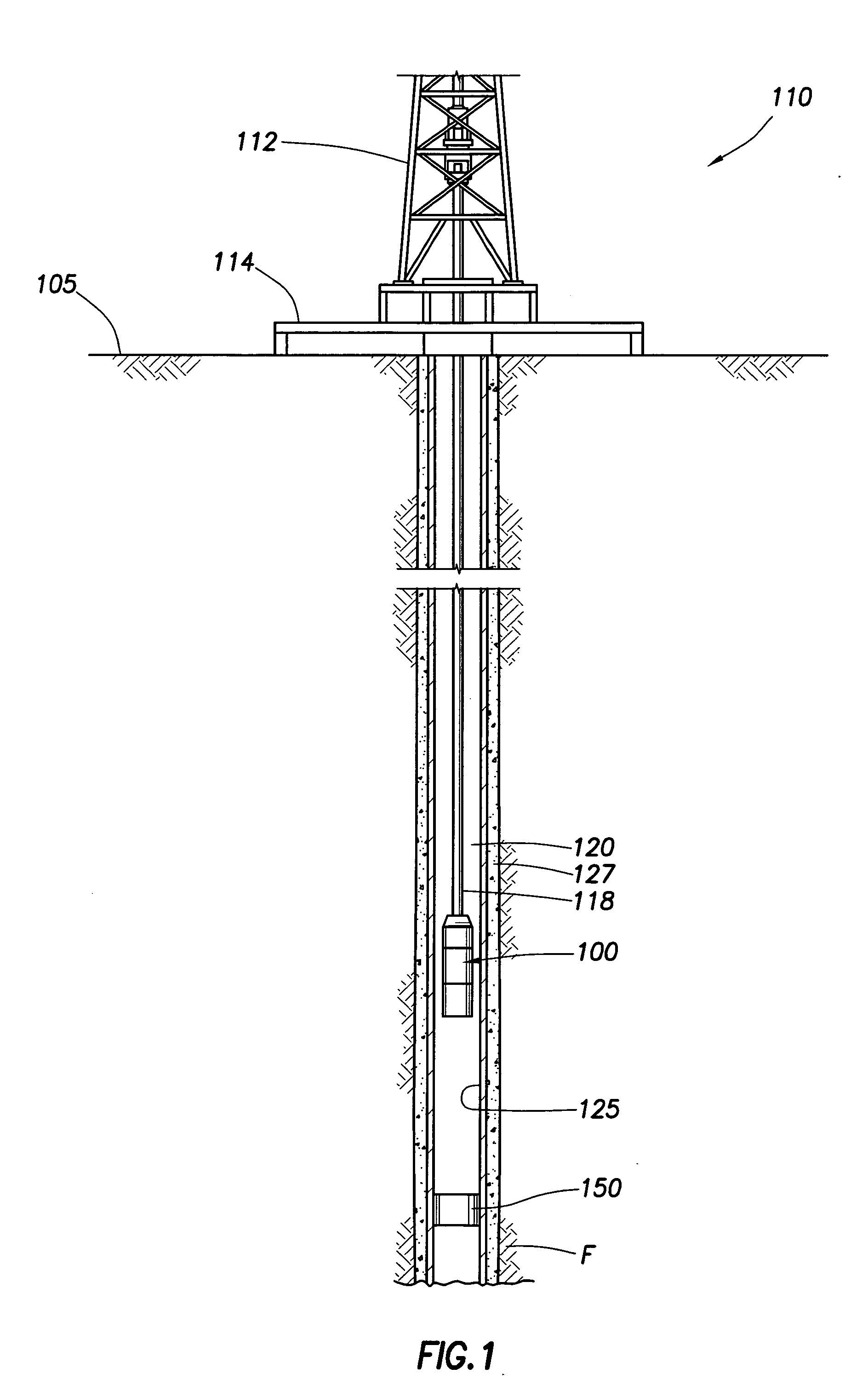
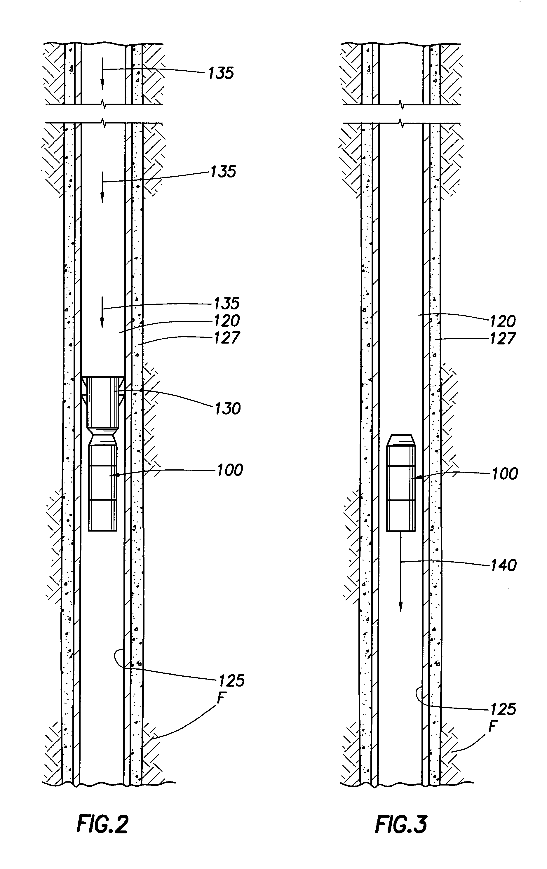
[0032] The present application relates to autonomous downhole tools that are moved at least a partial length along a well bore via an external force. In an embodiment, the autonomous downhole tool is moved along substantially the entire length of the well bore via an external force. In various embodiments, the external force is provided by a cable, by hydraulic pressure, by force of gravity, or by a combination thereof. In an embodiment, the autonomous downhole tool is not self-transportable via an onboard power supply. In an embodiment, the autonomous downhole tool is non-robotic. In an embodiment, the autonomous downhole tool does not provide its own locomotion. In an embodiment, the autonomous downhole tool is not self-propelling. In an embodiment, the autonomous downhole tool does not move within the well bore under its own power. In an embodiment, the autonomous downhole tool does not move within the well bore via traction with the well bore wall. In an embodiment, the autonomo...


PUM


Abstract

A method of servicing a well bore comprises deploying into the well bore a zonal isolation device operable to self-set at a sensed location, and self-setting the zonal isolation device to hold at the sensed location without receiving command communications from the surface, wherein the zonal isolation device is deployed along at least a partial length of the well bore via an external force. Another method of servicing comprises deploying into the well bore a tool operable to self-activate at one or more locations, and self-navigating the tool to determine the one or more locations without receiving communications from the surface, wherein the tool is moved along at least a partial length of the well bore via an external force.

Description

CROSS-REFERENCE TO RELATED APPLICATIONS [0001] The present application claims the benefit under 35 U.S.C. § 119(e) of U.S. Provisional Application Ser. No. 60 / 567,743 filed May 3, 2004 and entitled “Autonomous Navigation for a Downhole Tool,” by Wesley Jay Burris II, et al, which is incorporated herein by reference for all purposes.STATEMENT REGARDING FEDERALLY SPONSORED RESEARCH OR DEVELOPMENT [0002] Not applicable. REFERENCE TO A MICROFICHE APPENDIX [0003] Not applicable. FIELD OF THE INVENTION [0004] The present application relates to autonomous downhole tools that are moved in a well bore via an external force, and methods of servicing a well bore using such tools. The present application also relates to autonomous downhole tools that are self-navigating without receiving location communications from an external source, such as from the surface or another downhole component. The present application further relates to autonomous downhole tools that are self-activating without rec...

Claims


Application Information

Patent Timeline
Patent Type & Authority Applications(United States)
IPC IPC(8): E21B23/00E21B23/04E21B23/10E21B43/00E21B43/119E21B47/00E21B47/04E21B47/09
CPCE21B23/00E21B47/04E21B43/119E21B23/10
Inventor BURRIS, WESLEY J. IISCHWENDEMANN, KENNETH L.STARR, PHILLIP M.FRIPP, MICHAEL L.GOIFFON, JOHN J.HALES, JOHN H.RODGERS, JOHNTOWERS, DARRIN N.
Owner HALLIBURTON ENERGY SERVICES INC
Why Eureka
Try Eureka