

Concentrated winding stator coil for an electric rotary machine
a technology of electric rotary machines and stator coils, which is applied in the direction of windings, dynamo-electric components, synchronous machines, etc., can solve the problems of large bus bar accommodation space, difficult to perform such a wire connection work near the tooth coils or slots, and the possibility of the wires touching the rotor, etc., to achieve a simple and highly densified fashion.
- Summary
- Abstract
- Description
- Claims
- Application Information
AI Technical Summary
Benefits of technology
Problems solved by technology
Method used
Image

Examples
first embodiment
Overall Structure
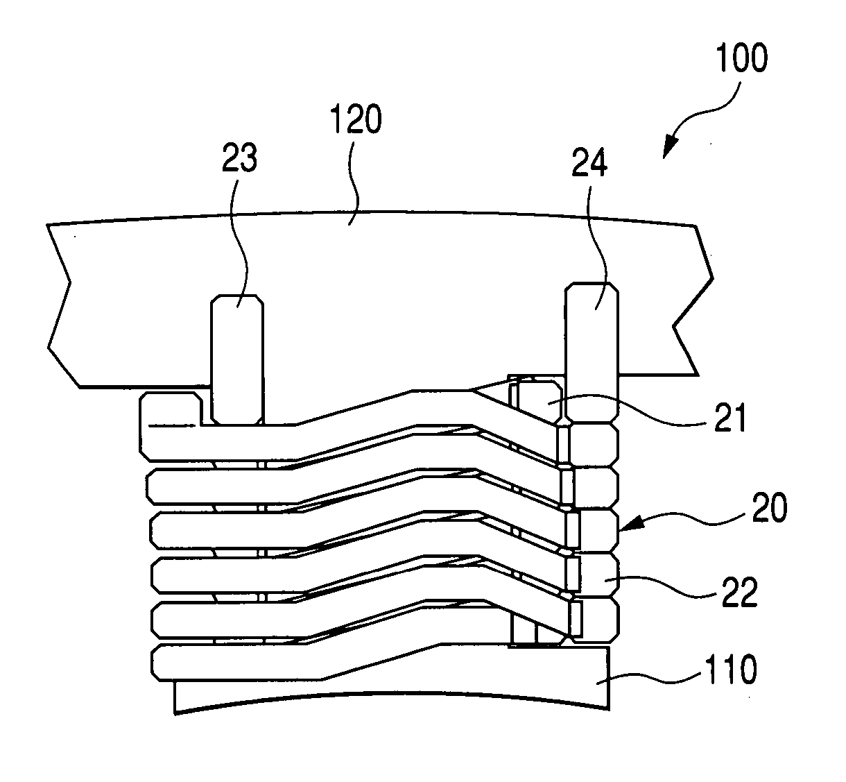
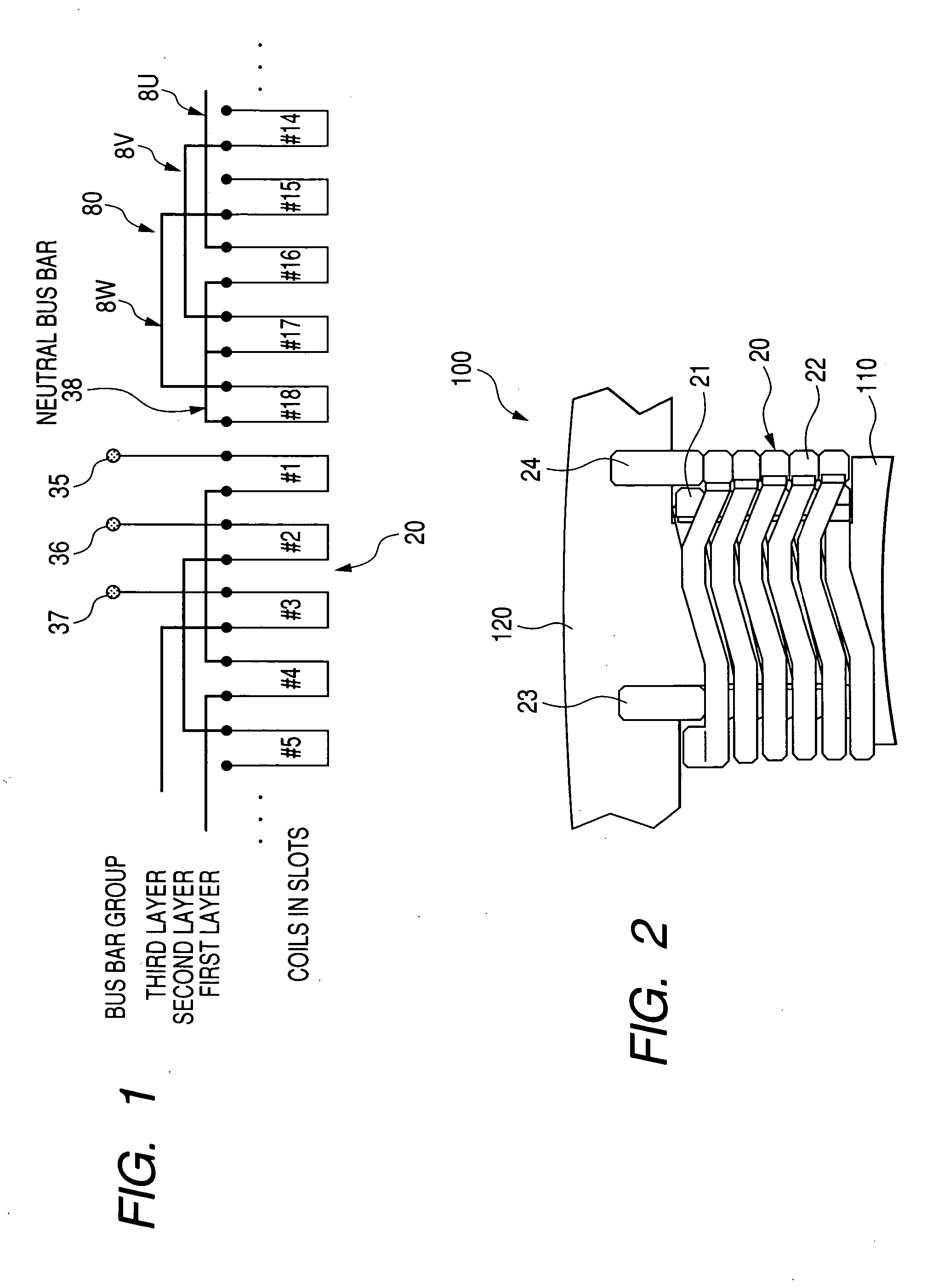
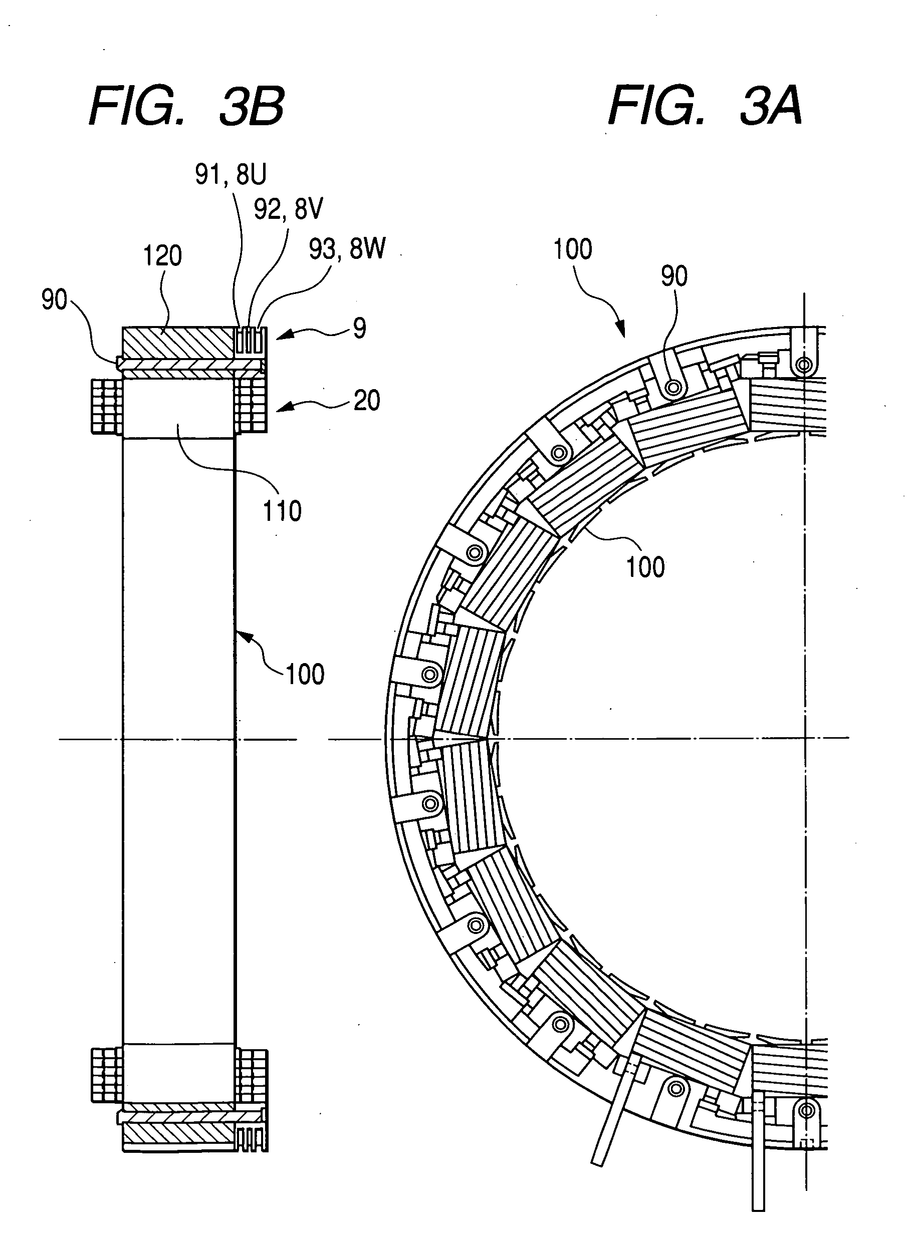
[0045] A concentrated winding stator having proximal end extraction type two-layer winding coils in accordance with a first embodiment of the present invention will be explained with reference to FIG. 1 showing a wiring arrangement, FIG. 2 showing an enlarged front view of a tooth and its periphery, FIG. 3A partly showing a front view of the stator, FIG. 3B showing a side cross-sectional view of the stator, and FIG. 4 partially showing an enlarged front view of a bus holder. A stator core 100 consists of a total of 18 teeth 110 and a single core back 120. The stator core 100 is arranged by multilayered electromagnetic steel plates. The stator core 100 has an assembled core structure, although FIG. 2 does not show the details of the assembled core structure.
[0046] Each tooth 110 protrudes inward in the radial direction from an inner cylindrical surface of the core back (i.e. yoke) 120. The teeth 110 are disposed at constant angular pitches in the circumferential di...
second embodiment
[0060] A second embodiment of the present invention will be explained with reference to FIGS. 5A and 5B. FIG. 5A is a front view of a concentrated winding stator including proximal end extraction type two-layer winding coils in accordance with the second embodiment. FIG. 5B is a cross-sectional view of the stator shown in FIG. 5A, taken along a plane extending in an axial direction. This embodiment is different from the above-described first embodiment in the arrangement of three-phase crossover bus bars. More specifically, according to this embodiment, the three-phase crossover bus bars are offset in the radial direction in a predetermined phase order. And, the crossover bus bars of the same phase are disposed at same positions in both axial and radial directions. On the other hand, according to the first embodiment, the three-phase crossover bus bars are offset in the axial direction in a predetermined phase order. And, the crossover bus bars of the same phase are disposed at same...
third embodiment
[0063] A third embodiment of the present invention will be explained with reference to FIG. 6. FIG. 6 is an enlarged cross-sectional view showing a crossover bus bar group 80 of a concentrated winding stator including proximal end extraction type two-layer winding coils according to this embodiment, taken along the axial direction.
[0064] This embodiment shows a modified example of the second embodiment which is characterized in that the crossover bus bars of each phase are offset in the radial direction in a predetermined phase order. According to this embodiment, respective bus bars consisting of the crossover bus bar group 80 and the neutral bus bar 38 (shown in the first embodiment) are flat type wires which have the cross section identical with that of the tooth coil 20 and are preferably sheathed with a resin coating film, and are formed by elongating the lead wires 23 and 24 extending from the tooth coils 20.
[0065] According to this embodiment, the radial width of the core b...
PUM
 Abstract
Description
Claims
Application Information