Polymeric Anti-Dazzle Raster For Tubular Light Sources

Inactive Publication Date: 2005-11-10
TARGETTI SANKEY
View PDF9 Cites 0 Cited by
  • Summary
  • Abstract
  • Description
  • Claims
  • Application Information

AI Technical Summary

Benefits of technology

[0004] The object of the present invention is to provide an antidazzle raster for tubular light sources that will not be associated with the assembling problems of metal rasters that have just bee

Problems solved by technology

These partitions have to be mounted one at a time on the side pieces of the raster, so that this type of antidazzle raster tends to be relatively costly.
Furthermore, the individual modules have to be independently attached to the body of the lamp body, so that the structure is rendered more complex and the lamp replacement becomes more laborious.

Method used


Image

  • Polymeric Anti-Dazzle Raster For Tubular Light Sources
  • Polymeric Anti-Dazzle Raster For Tubular Light Sources
  • Polymeric Anti-Dazzle Raster For Tubular Light Sources

Examples


Embodiment Construction

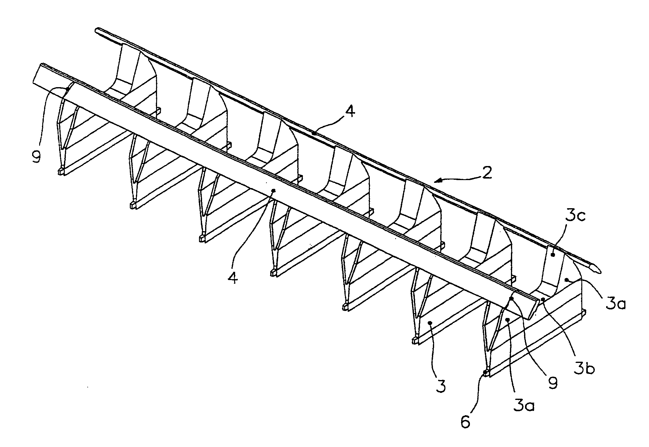
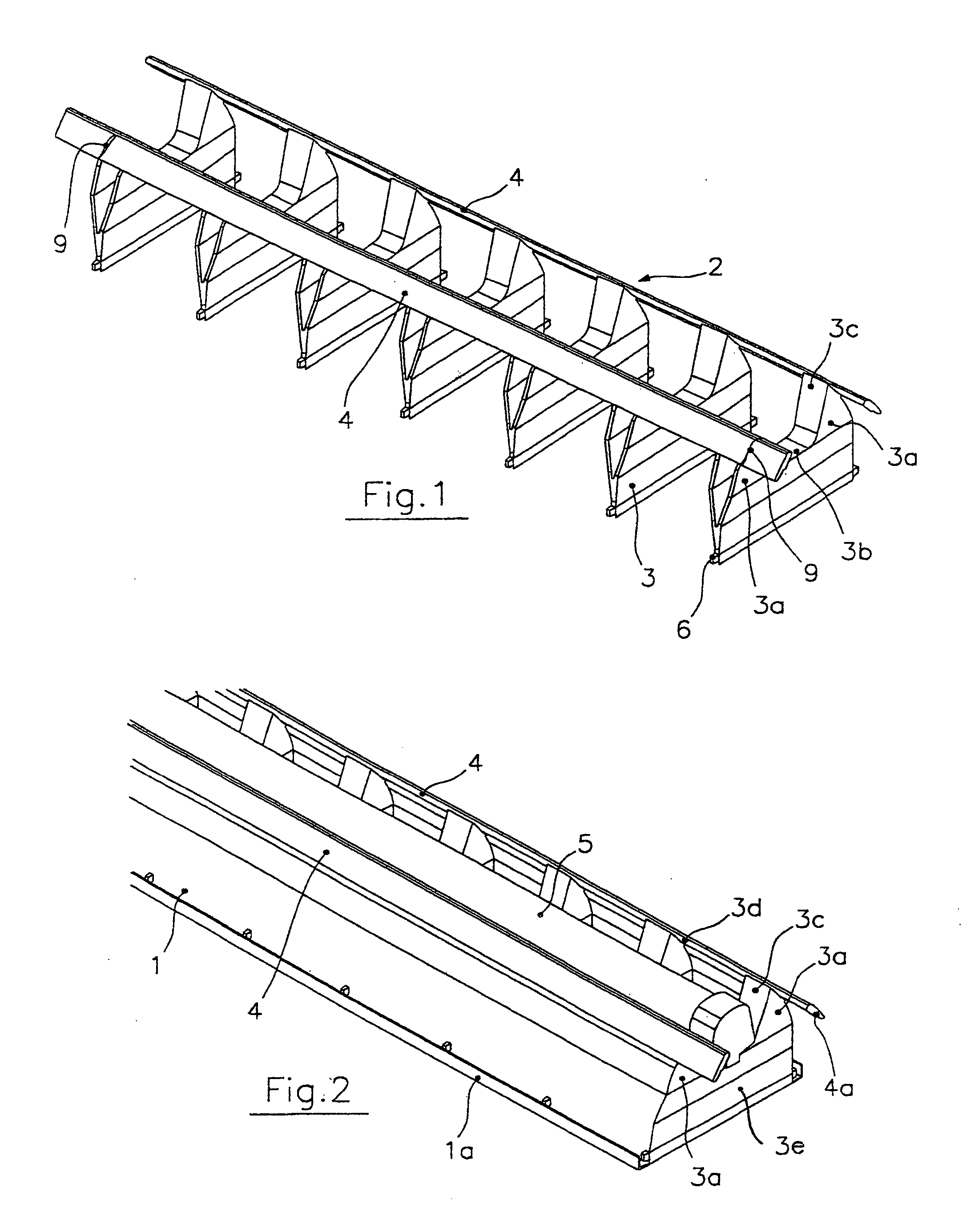
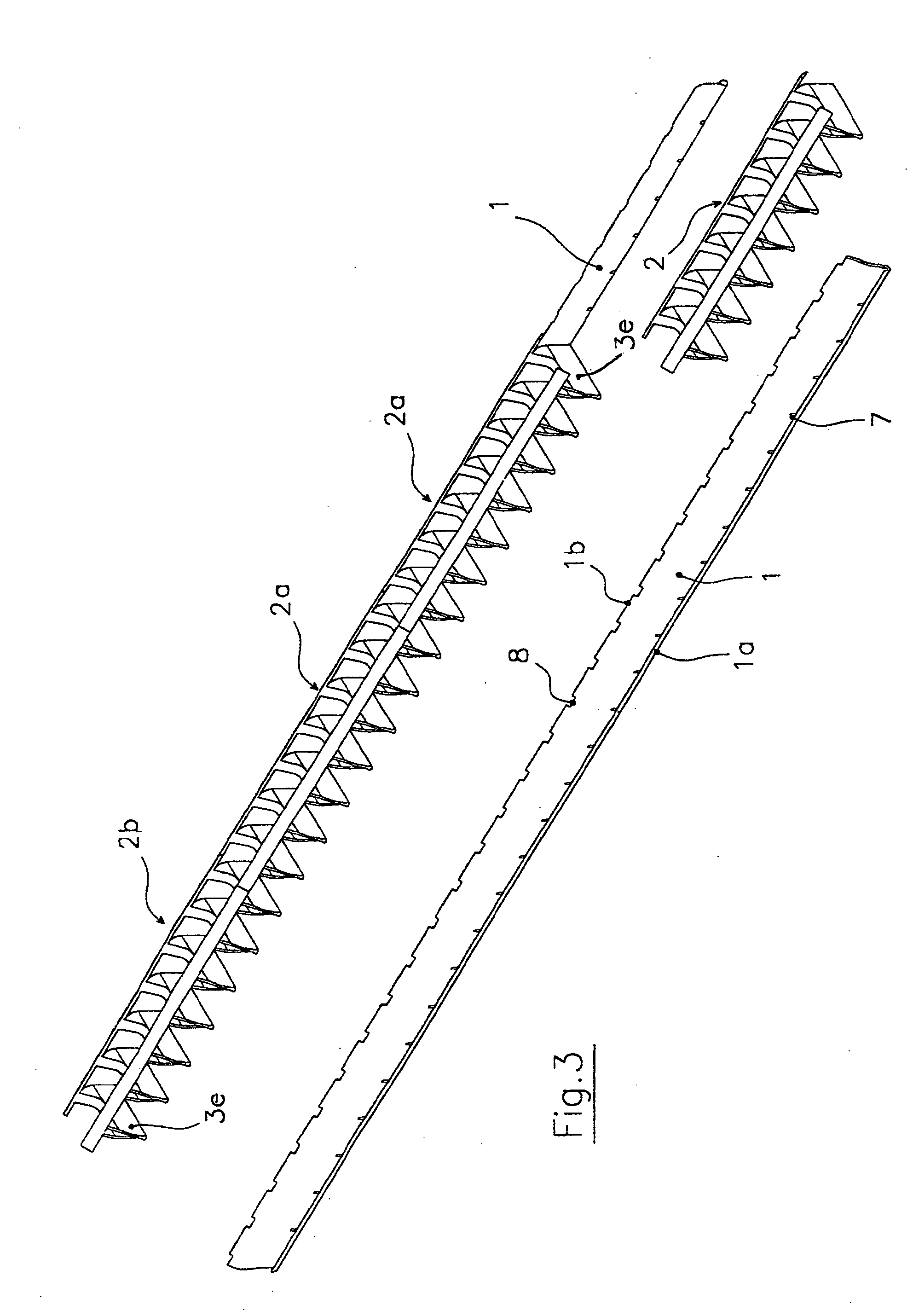
[0010] Referring to the above figures, the reference number 1 indicates the two side pieces of the antidazzle raster in accordance with the invention, made of aluminium sheeting, while 2 indicates a modular element made up of a certain number of parallel transverse partitions 3 set a constant distance apart and connected to each other by means of two bars 4. The partitions 3 and the bars 4 constitute a single piece made of plastic material, polycarbonate for example, by means of injection moulding.

[0011] Each transverse partition has a box-shaped configuration and a substantially V-shaped section with two symmetric shoulders 3a that extend from its upper edge 3b. The opposite internal faces 3c of each pair of shoulders 3a, together with the upper edge 3b of the respective partition, delimit a kind of channel in which there is accommodated the fluorescent lamp 5 shown only in FIG. 2. The bars 4, on the other hand, are attached to the outside faces 3d of the shoulders 3a of each part...


PUM


Abstract

An anti-dazzle raster for tubular light sources is disclosed. The raster comprises, for example, at least two side pieces and a plurality of transverse partitions that extend between the pieces. The side pieces are made of a relatively rigid and resistant material and the partitions are grouped into modular units. Each unit includes a selected number of partitions connected to one another by at least two generally parallel connection bars and to the side pieces by a snap fit. The modular units are formed of a selected plastic material using injection molding.

Description

FIELD OF THE INVENTION [0001] The present invention relates to an antidazzle raster for lighting fixtures making use of light sources that are tubular in shape, especially of the fluorescent type. DESCRIPTION OF THE PRIOR ART [0002] As is known, the antidazzle rasters, with which the greater part of the lighting fixtures with tubular light sources of the aforementioned type are equipped with, are typically made of aluminium sheeting and are constituted by two side pieces, generally of an arcuate profile, that are parallel and diverge from opposite parts with respect to the median plane in which the light source is situated and by a plurality of transverse partitions mounted by means of a snap fit in appropriate notches provided in the side pieces. The partitions may have a V-shaped section with transverse flaps bent back towards the interior for stiffening purposes. These partitions have to be mounted one at a time on the side pieces of the raster, so that this type of antidazzle ra...

Claims


Application Information

Patent Timeline
IPC IPC(8): F21V11/02F21V11/06F21V17/16
CPCF21V11/02F21Y2103/00F21V17/164F21V11/06
Inventor TARGETTI, PAOLO
Owner TARGETTI SANKEY
Why Eureka
Try Eureka