Brake pad wear indicator

a technology of wear indicator and brake pad, which is applied in the direction of brake elements, slack adjusters, brake members, etc., can solve the problem that the wear indicator does not take into account the wear of the inboard pad

Inactive Publication Date: 2005-11-17
MERITOR HEAVY VEHICLE BRAKING SYST (UK) LTD
View PDF8 Cites 24 Cited by
  • Summary
  • Abstract
  • Description
  • Claims
  • Application Information

AI Technical Summary

Benefits of technology

[0006] Another object of the present invention is to provide a brake pad wear indicator that can be retrofitted onto brake assemblies which either do not have brake pad wear indicators or have the above mentioned known wear indicator.

Problems solved by technology

However, such wear indicators do not take into account the wear of the inboard pad.

Method used


Image

  • Brake pad wear indicator
  • Brake pad wear indicator
  • Brake pad wear indicator

Examples


second embodiment

[0049]FIG. 6 shows a brake assembly 160 which includes the wear indicator assembly 66 of FIG. 4. However, in this case, the hexagonal recess 72 of the first component 67 engages a torque limiting device 83 which in turn engages a drive formation in the form of a hexagonal head 165 of a manual adjuster shaft 164. Torque limiting devices per se are known, and examples can be found in UK Patent GB2304387 and German Patent DE19923457C1. In summary, the torque limiting device 83 has a region 84 that engages the head 165 and a region 85 that is designed to be engaged by a tool, such as a spanner or hexagonal socket.

[0050] The torque limiting device 83 operates to prevent damage to the caliper as follows. When the brake pads have worn down to their service limit, they must be removed. To be able to insert the new, thicker brake pads, the adjuster mechanism must be de adjusted, and this is typically done by manually rotating the manually adjuster shaft 164. This is done by removing the wear...

third embodiment

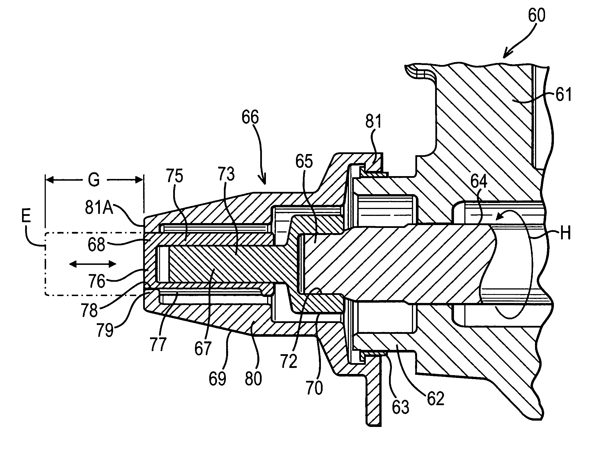
[0051]FIG. 7 shows a wear indicator assembly 266 which includes a first and second component identical to those shown in FIG. 4, but in this case a manual adjuster shaft cap body 280 sealingly engages in a recess 286 of a boss 270 of a sliding caliper 261. An elastomeric o-ring 287 provides sealing.

fourth embodiment

[0052]FIG. 8 shows a wear indicator assembly 360. The sliding caliper 61, the ring retainer 63 and the manual adjuster shaft 64 are identical to those shown in FIG. 4. The wear indicator assembly 360 includes a drive pin 90 having a boss 91 (similar to the boss 70) with a recess 92 (similar to the recess 72). However, a shaft 93 has a hexagonal cross section which acts as a drive formation 94. The drive formation 94 slidingly engages a hexagonal recess 96 in an indicator pin 95. An external surface 97 of the indicator pin 95 is threaded and threadingly engages a threaded internal surface of an end hole 98. A manual adjuster shaft cap 99 is rotationally fast with the sliding caliper 61. The indicator pin 95 and the drive pin 90 are both rotationally fast with the manual adjuster shaft 64. In this case, the external thread on the indicator pin 95 and the internal thread in the end hole 98 are both left hand threads. Thus, as the manual adjuster shaft 64 rotates in the direction of arr...


PUM


Abstract

A brake assembly includes a caliper, a brake pad, an actuator to force the brake pad into engagement with a rotor and an adjuster mechanism to compensate for wear of the brake pad. The adjuster mechanism includes a rotating component that rotates substantially in proportion to wear of the brake pad and is manually operable to deadjust the adjuster mechanism when replacement of the brake pad is required. The rotating component is operably coupled to a pad wear indicator mounted on the caliper which visually indicates an amount of brake pad wear.

Description

REFERENCE TO RELATED APPLICATIONS [0001] This application claims priority to United Kingdom Patent Application No. 0410659.7 filed on May 13, 2004. BACKGROUND OF THE INVENTION [0002] The present invention relates generally to a brake pad wear indicator, in particular for use on disc brake assemblies of heavy vehicles such as trucks and buses. [0003] Wear indicators are known wherein movement of a floating brake caliper (also known as a sliding brake caliper) in an inboard direction as an outboard pad wears can be detected by a wear indicator, allowing a comparison between a position of the floating caliper and a position of the fixed carrier upon which the floating caliper is slideably mounted to be made. However, such wear indicators do not take into account the wear of the inboard pad. SUMMARY OF THE INVENTION [0004] A brake assembly includes a calliper, a brake pad, an actuator to force the brake pad into engagement with a rotor and an adjuster mechanism to compensate for wear of...

Claims


Application Information

Patent Timeline
Patent Type & Authority Applications(United States)
IPC IPC(8): F16D65/46F16D65/02F16D65/56F16D66/00F16D66/02
CPCF16D65/568F16D2250/0084F16D2066/003F16D66/02
Inventor ENGLAND, TOM PETERTHOMAS, PAUL ANTHONYROBERTS, PAULFISHER, SIMON
Owner MERITOR HEAVY VEHICLE BRAKING SYST (UK) LTD
Why Eureka
Try Eureka