Data flow control

a data flow and control technology, applied in the field of data flow control, can solve the problems of data discarding being especially harmful, data throughput suffers, and not being ready to receive uplink data, so as to avoid or reduce too early resumption

a data flow and control technology, applied in the field of data flow control, can solve the problems of data discarding being especially harmful, data throughput suffers, and not being ready to receive uplink data, so as to avoid or reduce too early resumption

US20050254425A1Active Publication Date: 2005-11-17NOKIA TECHNOLOGLES OY

Image

  • Data flow control
  • Data flow control
  • Data flow control

Examples


Embodiment Construction

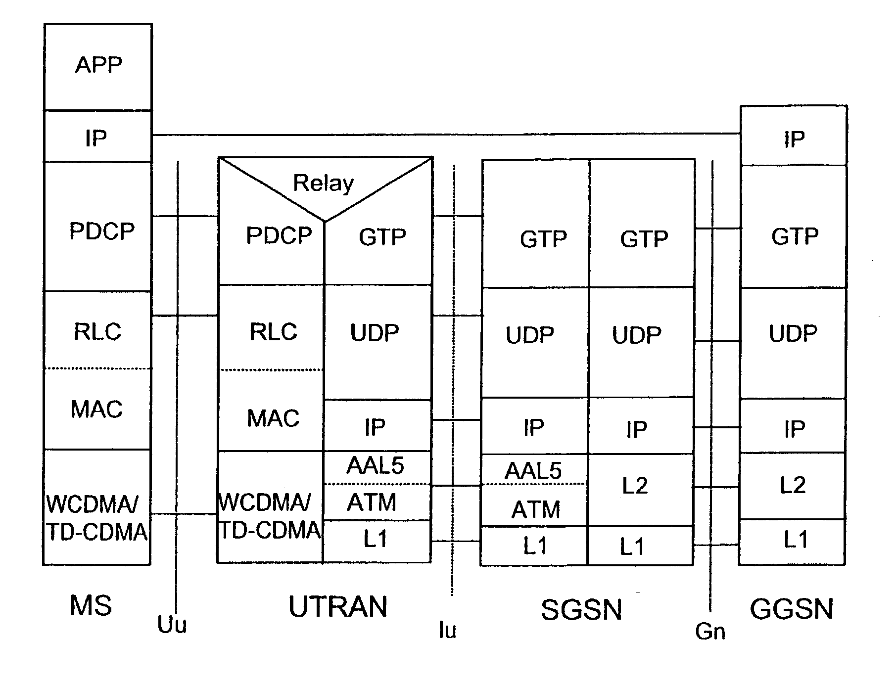
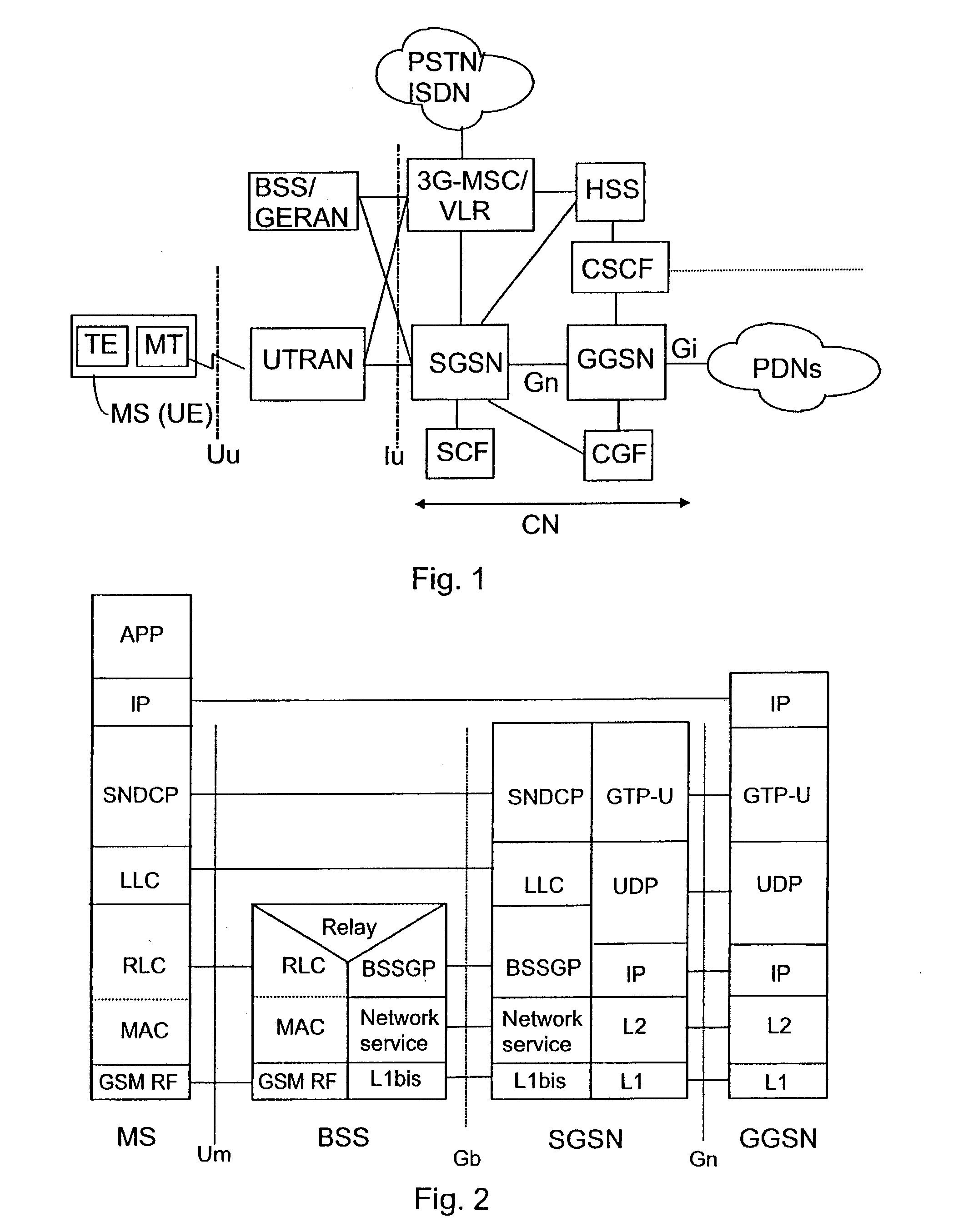
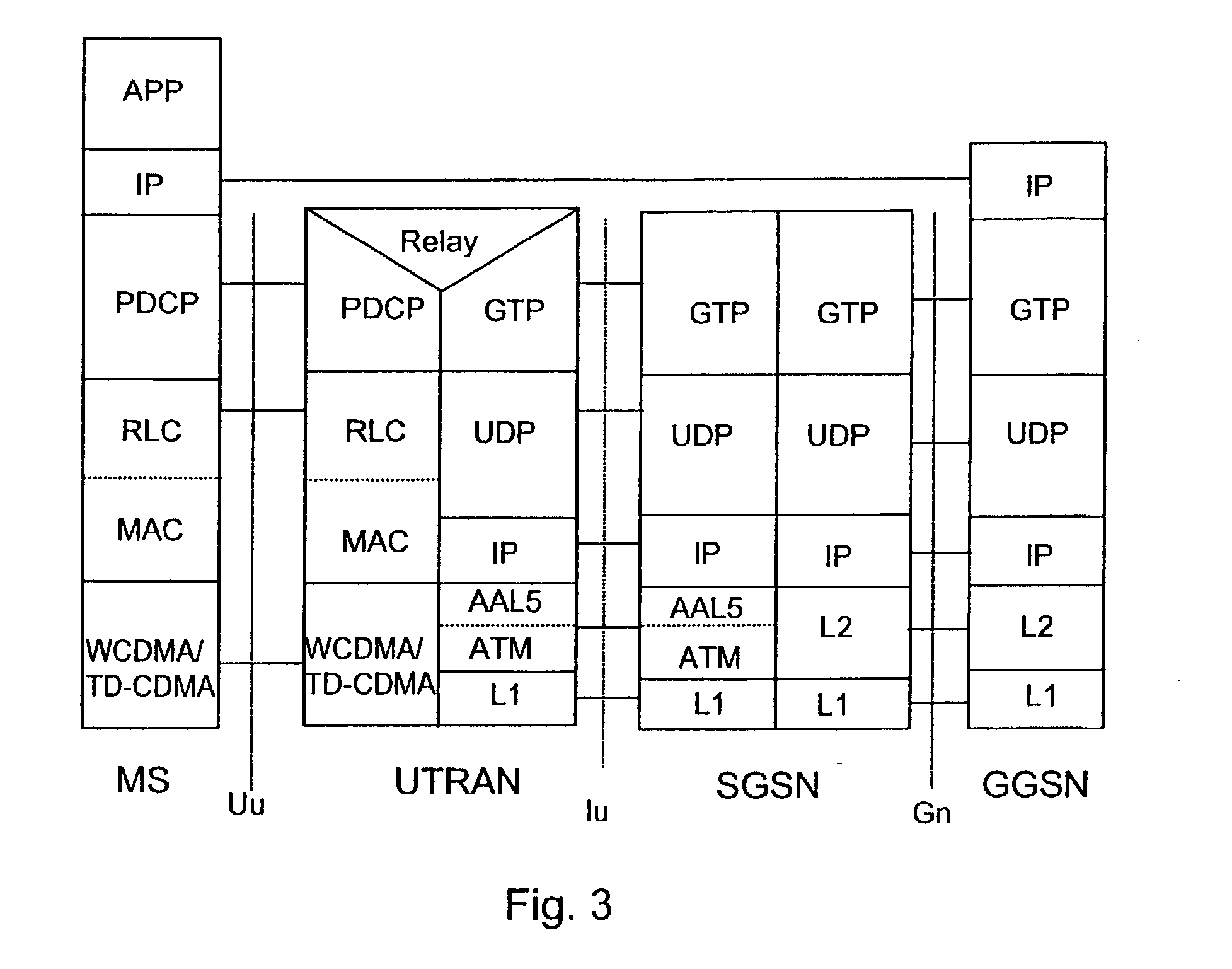
[0015] Reference is made to FIG. 1, wherein the main parts of a mobile system include a core network CN and a UMTS terrestrial radio access network UTRAN, which constitute the fixed network of the mobile system, and a mobile station MS, also called user equipment UE. The interface between the CN and the UTRAN is called Iu, and the air interface between the UTRAN and the MS is called Uu.

[0016] The UTRAN is typically composed of several radio network subsystems RNS, the interface between which is called Iur (not shown). The RNS is composed of a radio network controller RNC and one or more base stations BS, for which the term node B is also used. The interface between the RNC and the BS is called Iub. The base station BS attends to implementing the radio path and the radio network controller RNC manages radio resources. A connection to the UMTS core network CN can also be set up via a GSM base station subsystem BSS or a GSM / EDGE radio access network (Enhanced Data rates for GSM Evolut...


PUM


Abstract

The invention relates to arranging data flow control in a data transfer system comprising a sender and at least two protocol entities serving the transmission of data from the sender. The originating protocol entity of a suspension request primitive is checked. Suspension is set as the data transmission status for the protocol entity that has originated a suspension request primitive. The originating protocol entity of a resume request primitive is checked before sending it to the sender. Also the status information is checked. Transmission of the resume request primitive to the sender is prevented if suspension is set for any other protocol entity than the originating protocol entity of the resume request primitive.

Description

FIELD OF THE INVENTION [0001] The present invention relates to arranging data flow control, and more particularly to suspending and resuming data flows. BACKGROUND OF THE INVENTION [0002] In ordinary wireless data transmission the radio link level handles flow control, i.e. suspends and resumes the data flow. Usually a sender (either an internal application such as an MMS application (Multimedia Messaging Service) or an external dial-up device, e.g. a laptop) of the uplink data is faster than air interface, and an efficient flow control mechanism is needed for optimal data throughput. For arranging data flow control it is feasible to apply buffering and / or a suspension functionality. When suspension functionality is applied, the lower layer protocol entity may send a suspension request primitive to the sender which then suspends data transmission. In response to a resume request, the data transmission is resumed. [0003] In the 2nd generation GSM / GPRS and in the 3rd generation UMTS o...

Claims


Application Information

Patent Timeline
17 Nov 2005
Publication
US20050254425A1
IPC
H04L12/28; H04L12/56
CPC
H04L47/266; H04L47/10
Inventors
SUUMAKI, JAN; LAPPI, JOUNI