Level/position sensor and related electronic circuitry for interactive toy

Inactive Publication Date: 2005-11-17
FONG PETER SUI LUN
View PDF46 Cites 1 Cited by
  • Summary
  • Abstract
  • Description
  • Claims
  • Application Information

AI Technical Summary

Benefits of technology

[0007] In accordance with the present invention, there is provided a sensor for use in an interactive electronic device. The sensor is operative to generate a plurality of different output signals corresponding to respective positions of the sensor relative to a reference plane. The movement of the sensor relative to the reference plane facilitates the movement of one or more actuation balls of respective switches of the sensor, which in turn results in the generation of differing conditions or output signals corresponding to the particular pattern of electrical or conductive connection within the sensor facilitated by the switches thereof.

Problems solved by technology

However, in those prior art electronic toys including a motion actuated switch, such switch is typically capable of generating only a single output signal as a result of the movement of the toy.

Method used


Image

  • Level/position sensor and related electronic circuitry for interactive toy
  • Level/position sensor and related electronic circuitry for interactive toy
  • Level/position sensor and related electronic circuitry for interactive toy

Examples


first embodiment

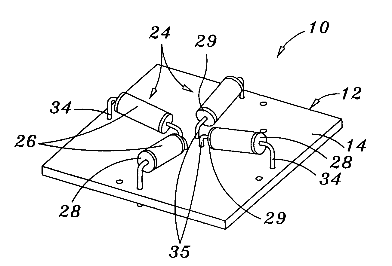
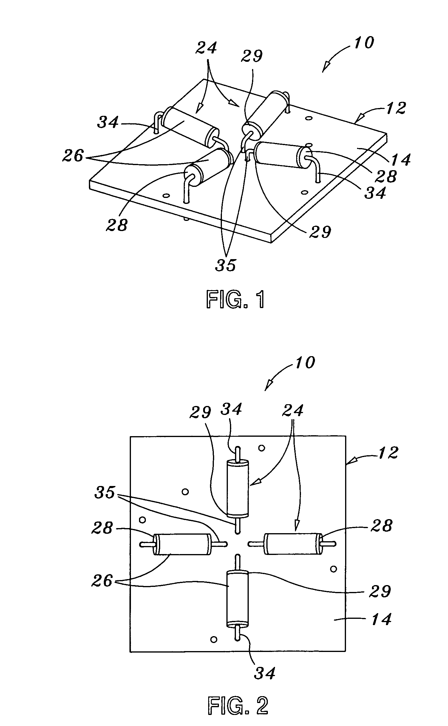
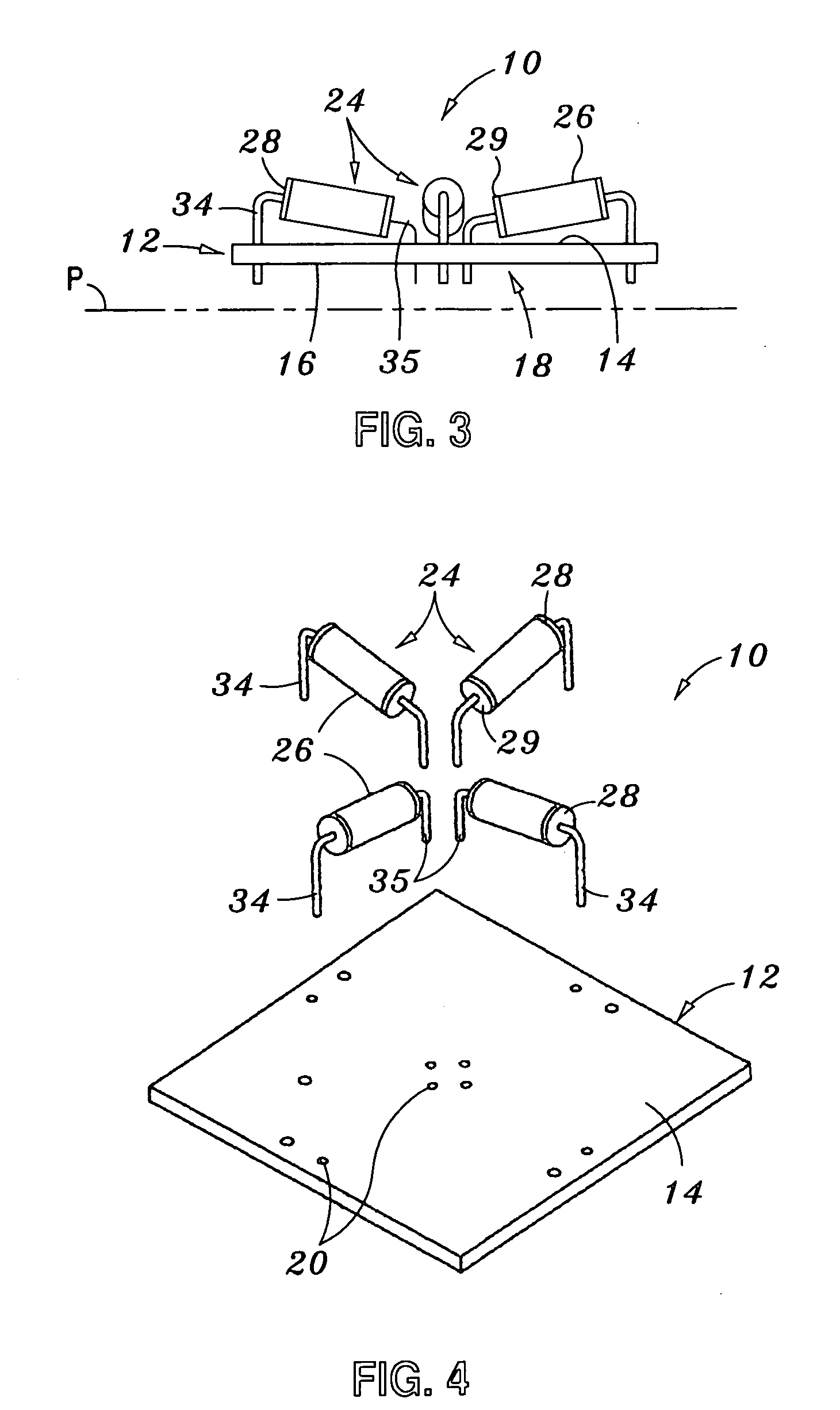
[0051] Referring now to the drawings wherein the showings are for purposes of illustrating preferred embodiments of the present invention only, and not for purposes of limiting the same, FIG. 1-4 perspectively illustrate a sensor 10 constructed in accordance with the present invention. The sensor 10 comprises a base plate 12 which, as seen in FIGS. 1-4, has a generally quadrangular (e.g., square) configuration. The base plate 12 defines a generally planar top surface 14 and an opposed, generally planar bottom surface 16. Formed on the bottom surface 16 of the base plate 12 is a conductive pattern 18 which may comprise one or more conductive pads and / or one or more conductive traces which is / are arranged in any one of a multiplicity of differently arranged patterns, the present invention not being limited to any prescribed pattern for the conductive pattern 18. The conductive pattern 18 is preferably fabricated from a conductive metallic material, such as copper. The formation of the...

third embodiment

[0066] As will be recognized, the electronic circuitry with which the sensor 10b is used will be adapted to accommodate the additional output signals that will be generated by the sensor 10b as a result of the increased number of switches 24 therein. Though not shown, those of ordinary skill in the art will recognize that a contemplated variant of the sensor 10b is one which further includes a thirteenth switch 24 which extends generally perpendicularly relative to the top surface 14 of the base plate 12. Though also not shown, the sensor 10b of the third embodiment may be alternatively configured such that the switches 24 are positioned on only the bottom surface 16 of the base plate 12, or on both the top and bottom 14, 16, as discussed above in relation to the sensor 10. Additionally, though in the sensor 10 four switches are included, and in the sensor 10b twelve switches are included, those of ordinary skill in the art will further recognize that sensors including fewer than fo...

sixth embodiment

[0071] In the sensor 46 of the sixth embodiment, the separate base members 48 (which each include a switch 24 interfaced thereto in the above-described manner) are preferably attached to a common support or platform 60. Such platform 60 may actually comprise a toy or other device into which the sensor 46 is integrated. Those of ordinary skill in the art will recognize that the platform 60 need not necessarily be a unitary structure, but may consist of multiple structures which are interfaced to each other so as to concurrently move with each other. In this regard, all that is necessary is that the switches 24 and corresponding base members 48 always move concurrently when the toy or other device into which the sensor 46 is integrated is moved or shifted relative to a reference plane. The base members 48 are preferably attached to the platform 60 such that switches 24 are spaced from each other at intervals of approximately ninety degrees.

[0072] The sensor 46 of the sixth embodiment ...


PUM


Abstract

A sensor for use in an interactive electronic device. The sensor is operative to generate a plurality of different output signals corresponding to respective positions of the sensor relative to a reference plane. The movement of the sensor relative to the reference plane facilitates the movement of one or more actuation balls of respective switches of the sensor, which in turn results in the generation of differing conditions or output signals corresponding to closed or open circuit conditions selectively created by the switches.

Description

CROSS-REFERENCE TO RELATED APPLICATIONS [0001] The present application is a continuation-in-part of U.S. application Ser. No. 10 / 872,015 entitled LEVEL / POSITION SENSOR AND RELATED ELECTRONIC CIRCUITRY FOR INTERACTIVE TOY filed Jun. 18, 2004, which is a continuation-in-part of U.S. application Ser. No. 10 / 628,007 entitled LEVEL / POSITION SENSOR AND RELATED ELECTRONIC CIRCUITRY FOR INTERACTIVE TOY filed Jul. 25, 2003, which claims priority to U.S. Provisional Application Ser. No. 60 / 398,372 entitled LEVEL / POSITION SENSOR AND RELATED ELECTRONIC CIRCUITRY FOR INTERACTIVE TOY filed Jul. 25, 2002, and is a continuation-in-part of U.S. application Ser. No. 10 / 179,569 entitled LEVEL / POSITION SENSOR AND RELATED ELECTRONIC CIRCUITRY FOR INTERACTIVE TOY filed Jun. 25, 2002, which is a continuation of U.S. application Ser. No. 09 / 568,900 entitled LEVEL / POSITION SENSOR AND RELATED ELECTRONIC CIRCUITRY FOR INTERACTIVE TOY filed May 11, 2000 and issued as U.S. Pat. No. 6,437,703 on Aug. 20, 2002, w...

Claims


Application Information

Patent Timeline
IPC IPC(8): A63H30/00H01H35/02H05K1/18
CPCH01H35/025H05K1/18H05K2201/10522H05K2201/10151H05K2201/10484H05K2201/10053
Inventor LUN, PETER SUI
Owner FONG PETER SUI LUN
Why Eureka
Try Eureka