Multi-layer super resolution optical disc

a super-resolution, optical disc technology, applied in the direction of mechanical recording, carpet cleaning, instruments, etc., can solve the problems of reducing the quality of the reproduction signal of the optical disc, the border between the outer periphery of the marks and the space between the marks is poorly defined, and the recording marks are not uniform, etc., to achieve the effect of enhancing the recording density

Inactive Publication Date: 2005-11-24
LG ELECTRONICS INC
View PDF5 Cites 20 Cited by
  • Summary
  • Abstract
  • Description
  • Claims
  • Application Information

AI Technical Summary

Benefits of technology

[0023] The present invention has been made to solve the above problems, and it is an object of the present invention to provide a super resolution optical disc, which is capable of enhancing the recording density by employing a multi-layer structure.
[0024] It is further object of the present invention to provide a super resolution optical disc, which is capable of enhancing the quality of the reproduction signal for recording marks.
[0025] It is another object of the present invention to provide a super resolution optical disc, in which the difference of the reflection rate between central portion and outer portion of the recording marks gets smaller and the border between the recording marks and spaces becomes well defined.

Problems solved by technology

Due to such a non-uniform expansion of the mask layer, the recording marks are not uniform, and the reflection rate differs between the center of the marks and the outer periphery thereof.
Moreover, the border between the outer periphery of the marks and the space between the marks is poorly defined.
Accordingly, there are problems in that the quality of the reproduction signal of the optical disc is lowered and in that integrity of reproduction performance cannot be secured.
Moreover, although there have been continuous efforts to increase the storage capacity of the super resolution optical disc, an effective solution for this problem has not been discovered yet.

Method used


Image

  • Multi-layer super resolution optical disc
  • Multi-layer super resolution optical disc
  • Multi-layer super resolution optical disc

Examples


Embodiment Construction

[0037] Preferred embodiments will now be described in detail with reference to the accompanying drawings.

[0038] In accordance with the present invention, a multi-layer super resolution optical disc comprises a plurality of layers and intermediate layers formed between the layers.

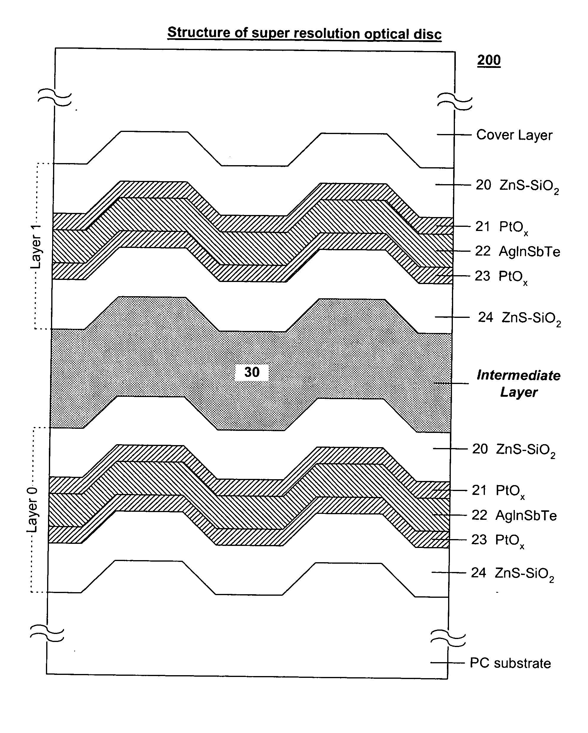
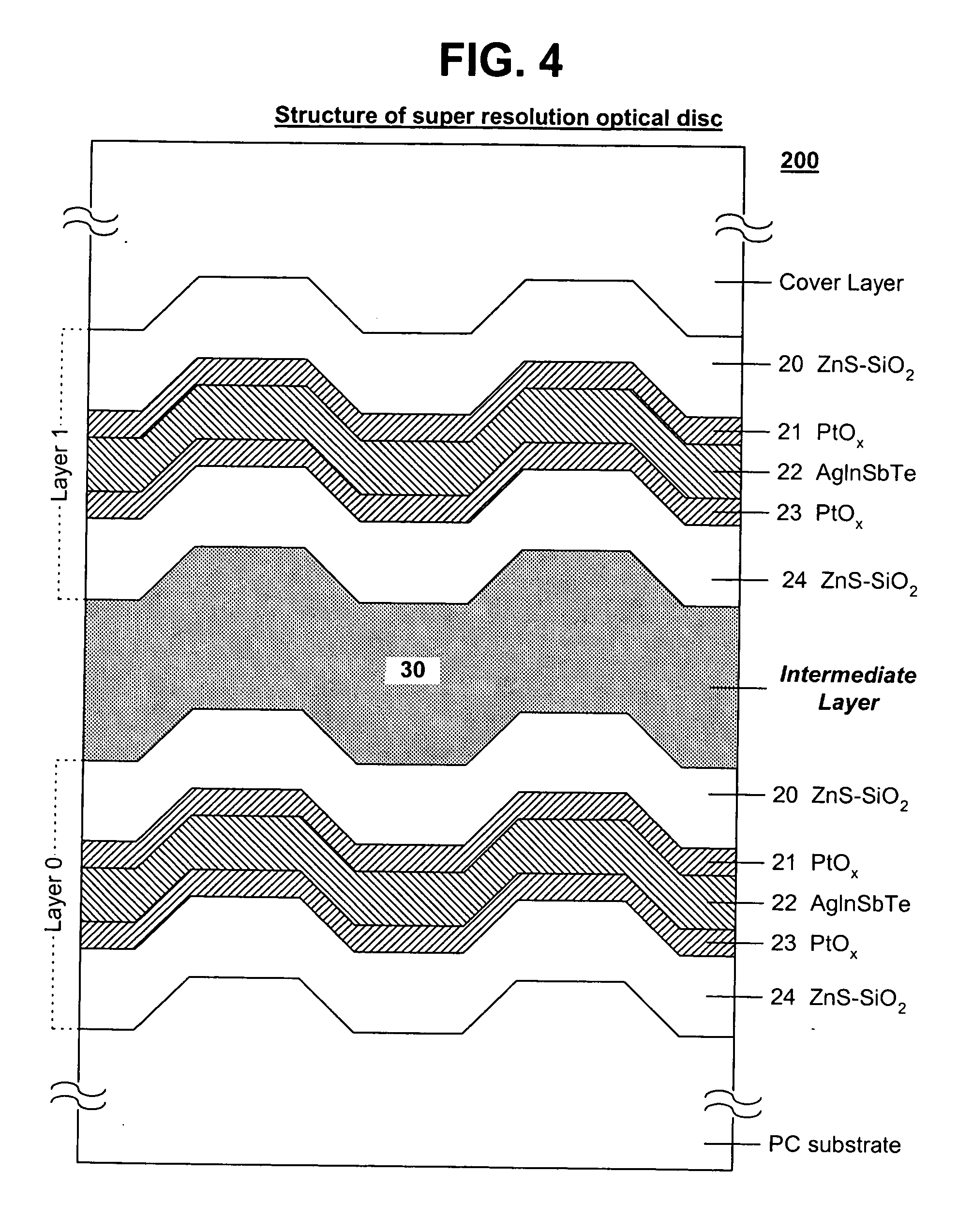
[0039] For example, a dual-layer super resolution optical disc in accordance with one embodiment of the present invention comprises a first layer (Layer 0) and a second layer (Layer 1), in each of which a first dielectric layer 20, a first mask layer 21, an impact absorption layer 22, a second mask layer 23, and a second dielectric layer 24 are sequentially laminated, as shown in FIG. 4.

[0040] And, an intermediate layer (a spacer or a space layer) is formed between the first layer and the second layer in the dual-layer super resolution optical disc. The intermediate layer may consist of polymer material thermo-set by ultraviolet rays, and the thickness of the intermediate layer may be in range of 10 um to...


PUM

PropertyMeasurementUnit
thicknessaaaaaaaaaa
temperatureaaaaaaaaaa
melting pointaaaaaaaaaa

Abstract

Disclosed is a multi-layer super resolution optical disc. In the multi-layer super resolution optical disc, at least two recording layers, each of which comprises at least two mask layers and impact absorption layers formed between the mask layers, are laminated, and intermediate layers of polymer thermo-set by ultraviolet rays are formed between the recording layers. Accordingly, jitter characteristics for recording marks are improved, and recording density is enhanced.

Description

BACKGROUND OF THE INVENTION [0001] 1. Field of the Invention [0002] The present invention relates to an optical recording medium, and more particularly to a multi-layer super resolution optical disc, which has enhanced signal quality and enhanced recording density. [0003] 2. Description of the Related Art [0004] Generally, currently available optical discs have a storage capacity of about 4.7 GB (gigabytes) in the DVD (Digital Versatile Disc) standard using red laser or of about 25 GB in the BD (Blue-ray Disc) standard using blue laser, which has been commercialized recently. However, in order to record and reproduce a huge amount of information for applications, such as high definition TV or E-medicine, there is a need to provide an information storage technology with a higher density. [0005] For instance, in order to record a data stream of high definition digital video, recently available on the market, there is a need to provide a storage medium, which has a storage capacity of ...

Claims


Application Information

Patent Timeline
Patent Type & Authority Applications(United States)
IPC IPC(8): G11B7/24G11B7/243G11B7/257G11B7/26
CPCG11B7/24G11B7/24038G11B7/243G11B7/2534G11B7/257G11B2007/25715G11B2007/2431G11B2007/24314G11B2007/24316G11B2007/25706G11B2007/24308A47L13/225A47L11/4075A47L2601/04
Inventor AHN, KUN HOKWAK, KEUM CHEOL
Owner LG ELECTRONICS INC
Why Eureka
Try Eureka