Recording medium, optical disk apparatus and writing method

a technology of optical disk and recording medium, applied in the direction of recording strategy, recording signal processing, instruments, etc., can solve the problems of not being able to obtain the optimal recording parameter, the optimal recording parameter recorded on the medium in advance is not optimal, and the method of obtaining the optimal recording parameter is not considered. , to achieve the effect of simple write strategy setting method, stable reproduction, and easy calculation of recording parameters

Inactive Publication Date: 2008-02-14
HITACHI CONSUMER ELECTRONICS CORP
View PDF9 Cites 17 Cited by
  • Summary
  • Abstract
  • Description
  • Claims
  • Application Information

AI Technical Summary

Benefits of technology

[0017] A second object of the present invention is to assure continuity of recording parameters, assure continuity of the recording mark shape, and improve the reproduction quality.
[0023] The present invention assures continuity of the shape of a reproduction waveform, thereby enabling stable reproduction. Moreover, it is possible to easily calculate a recording parameter at a recording velocity other than the recording velocity where the recording parameters provided by a medium manufacturer are defined, from the recording parameters provided by the medium manufacturer. Accordingly, when performing CAV recording, it is possible to calculate a preferable recording parameter.
[0024] Moreover, for a drive manufacturer, it is possible to simplify the write strategy setting method when realizing a high velocity recording by the CAV recording, reduce the drive development time, and reduce the learning time when adjusting the write strategy in the drive.
[0025] Moreover, by using the procedures of the present invention in the drive, it is possible to calculate the write strategy and the recording parameter coping with the variable velocity recording so as to realize a variable velocity recording such as CAV recording in a medium not having any recording parameters provided by a medium manufacturer coping with the variable velocity recording. Furthermore, by referencing the variable velocity recording flag, it is possible to easily identify a medium supporting the variable velocity recording and reduce the write strategy learning time when performing the variable velocity recording.

Problems solved by technology

Accordingly, the optimal recording parameter in a particular drive may not be the optimal recording parameter in another drive.
When recording information onto the recording medium at a linear velocity other than the particular linear velocity, the recording parameter recorded on the medium in advance is not optimal.
However, in the drive for recording information on a recording medium where an optimal recording parameter at a particular linear velocity is described, conventionally, no consideration has been taken on the method to obtain an optimal recording parameter at a linear velocity other than the particular linear velocity at the drive side.

Method used


Image

  • Recording medium, optical disk apparatus and writing method
  • Recording medium, optical disk apparatus and writing method
  • Recording medium, optical disk apparatus and writing method

Examples


embodiment 1

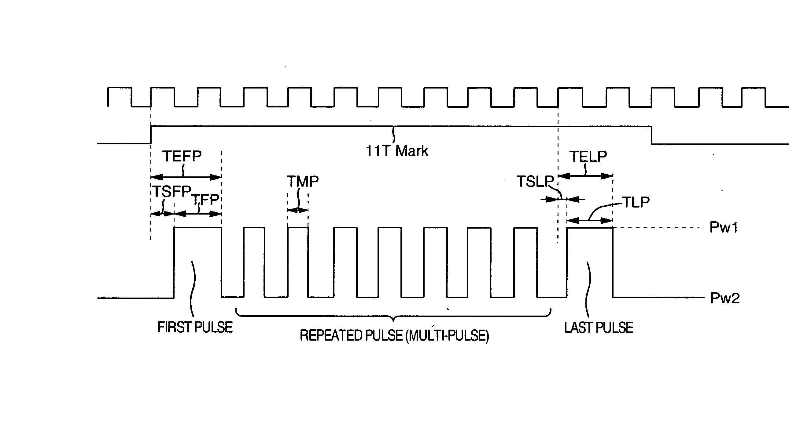
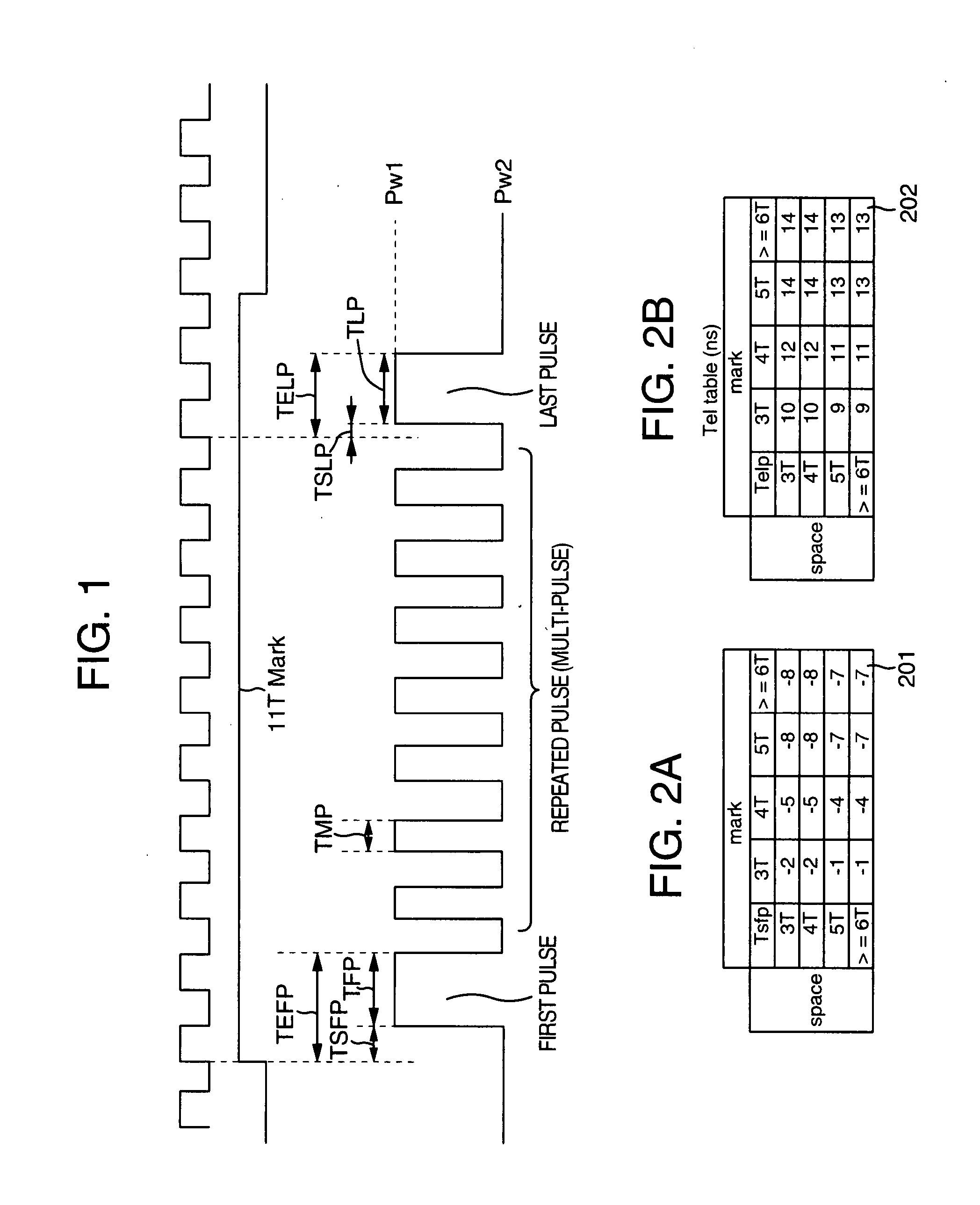
[0039] Explanation will be given on the first embodiment by using the DVD-RAM as an example. As has been described above, in the DVD-RAM, the recording parameter is selected by a medium manufacturer and shipped.

[0040] Currently, as the DVD-RAM standard, double speed (hereinafter, referred to as “2×”) recording standard and triple speed (hereinafter, referred to as “3×”) recording standard are released. Release of five-times speed (hereinafter, referred to as “5×”) recording standard is expected. That is, the 5× recording disk (hereinafter, referred to as DVD-RAM 5×) is probably provided with the 2× recording and 3× recording parameter, considering the compatibility with a lower apparatus. Moreover, by using the recording parameters of the respective recording velocities, in the 5× recording drive, it is possible to perform CAV recording with recording velocity of 2× at the innermost circumference and 5× at the outermost circumference. An example of recording parameter decision proc...

embodiment 2

[0068] Next, explanation will be given on a second embodiment. The second embodiment also sets recording parameters in the same way as the first embodiment. However, the procedure 2 is different from that of the first embodiment. Hereinafter, explanation will be given on the procedure 2.

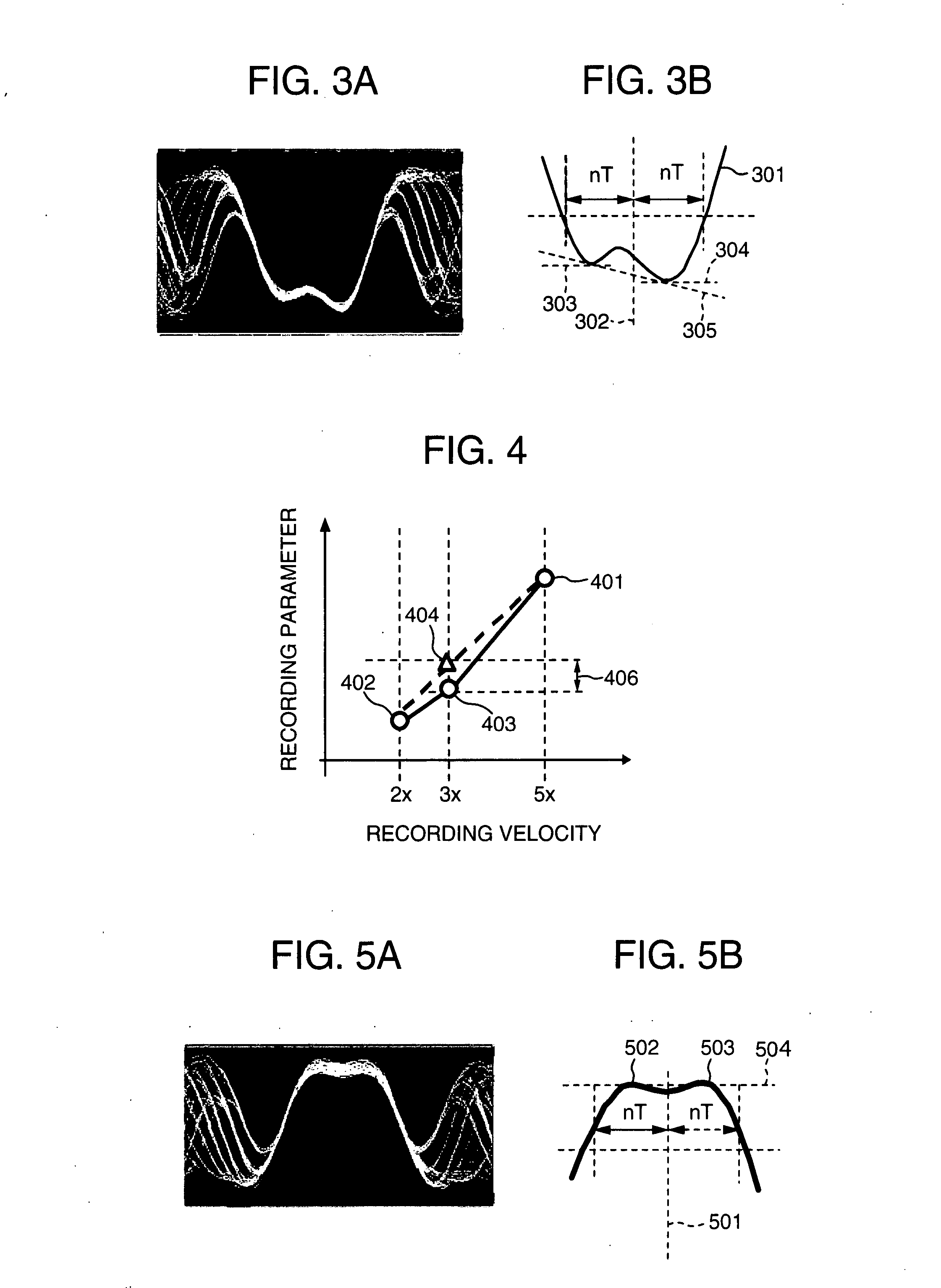
[0069] In the procedure 2 of the first embodiment, by monitoring the reproduction waveform of the long mark of 6T or above recorded by using the recording parameters of different velocities, the inclination of the mark portion is substantially matched between the recording velocities. In the present embodiment, the inclination of the reproduction waveform of the long mark of 6T or above is compared to the long space portion of 6T or above or the inclination of the reproduction waveform of a reserved area, thereby deciding an optimal recording parameter.

[0070] For example, in the case of the space portion, as shown in FIG. 5, the center of the space portion waveform 501, i.e., in the case of 10T spa...

embodiment 3

[0073] Next, explanation will be given on a third embodiment. In this embodiment, the recording parameter setting method and variable velocity recording bit are identical to the first embodiment. However, the method for checking the recording parameter linearity in the procedures 2 and 4 is different. Hereinafter, explanation will be given on the procedures 2 and 4.

[0074] In the procedure 2 of the first embodiment, a difference between the recording parameter obtained by the linear interpolation and the recording parameter obtained by a condition of the waveform inclination defined for the long mark reproduction waveform of 6T or above is compared to a predetermined error allowance value to judge the linearity of the recording parameter.

[0075] The procedure 2 of the present embodiment calculates only a basic recording parameter (which is made basic recording parameter A) at the medium maximum recording velocity (5× recording in this embodiment) and a basic recording parameter (whi...


PUM

PropertyMeasurementUnit
lengthaaaaaaaaaa
lengthaaaaaaaaaa
lengthaaaaaaaaaa

Abstract

Recording parameters are decided so that the time control information on at least the front edge and the rear edge of a parameter forming a mark of twice size or above of the laser spot diameter focused on the recording medium is substantially proportional to the recording linear velocity. The mark is recorded and reproduced at a predetermined linear velocity to obtain an electric signal waveform having a time width Tm. A parameter is decided so as to control the laser pulse for recording information so that a voltage value change amount at two points at a distance Ts (Ts<Tm / 2) in the time axis direction before and after the time position Tm / 2 from the front edge of the waveform is substantially constant for the recording linear velocity change. Identification information indicating the parameter is described on the recording medium.

Description

BACKGROUND OF THE INVENTION [0001] The present invention relates to a technique for recording information onto an optical disk by using a laser beam. [0002] In a rewritable optical disk such as DVD-RAM, DVD-RW, CD-RW and a write once disk such as DVD-R and CD-R, information is recorded by applying a laser beam onto the disk recording surface. As the laser beam application method for forming a recording mark on the recording surface of the optical disk, there is a CD-R method for forming a recording mark by applying a recording pulse having time width according to the length of the recording mark, a DVD-RAM method for making the recording mark forming pulse comb-shape so as to control head accumulation and to form an optimal recording mark, and the like. The waveform of the recording pulse to obtain the optimal recording mark is called write strategy. [0003]FIG. 1 schematically shows a write strategy of 4.7 GB-capacity DVD-RAM (hereinafter, referred to simply as DVD-RAM) which is one...

Claims


Application Information

Patent Timeline
Patent Type & Authority Applications(United States)
IPC IPC(8): G11B5/00G11B7/24G11B7/0045G11B7/007G11B7/125G11B7/1267
CPCG11B7/00456G11B7/1267G11B7/00736
Inventor NISHIMURA, KOICHIROKUREBAYASHI, MASAAKITODA, TSUYOSHIMINEMURA, HIROYUKI
Owner HITACHI CONSUMER ELECTRONICS CORP
Why Eureka
Try Eureka