Device for cooling an optical module for a motor vehicle headlight

a technology for cooling optical modules and headlights, which is applied in the direction of indirect heat exchangers, semiconductor devices for light sources, lighting and heating apparatus, etc., can solve the problems of increasing the weight and overall dimensions of optical modules, affecting the installation of this type of devices, and reducing the flow of light, so as to improve the efficiency of cooling the flow of cold air and facilitate positioning. , the effect of high thermal conductivity

Active Publication Date: 2010-06-24
VALEO VISION SA
View PDF13 Cites 22 Cited by
  • Summary
  • Abstract
  • Description
  • Claims
  • Application Information

AI Technical Summary

Benefits of technology

[0031]Preferably, the deflectors have a high level of thermal conductivity, i.e., greater than 10 W / m / ° C. (10 Watts per meter per degree Celsius). The deflectors thus also have a function of dissipation of the negative calories obtained from the proximal end of the heat conductor, therefore making it possible to cool the flow of cold air more efficiently.
[0032]The deflectors are each advantageously formed by a plate through which the first end of the heat pipe passes. As seen in the preceding paragraph, this metal plate has in particular characteristics of thermal conductivity which are high, i.e., greater than 10 W / m / / ° C., whilst being formed, for example, from a sheet of metal. The physical contact between the metal plate and the heat pipe which passes through it makes it possible not only to obtain an easy positioning of the metal plate axially on the heat pipe, but also to assist the dissipation of the negative calories obtained from the heat pipe.

Problems solved by technology

However, during functioning, the LEDs produce heat which is detrimental to their operation, since the more the temperature of an LED increases, the more its flow of light decreases.
However, this solution has the disadvantage of resulting in a consequent increase in the weight and overall dimensions of the optical module, which should be avoided in order to facilitate installation of the module inside the housing.
Installation of this type may be made problematic because of shortage of space available for receipt of the optical module(s), and / or because of the constraints associated with the overall arrangement of the headlight in relation to its close environment when it is fitted on the vehicle.

Method used


Image

  • Device for cooling an optical module for a motor vehicle headlight
  • Device for cooling an optical module for a motor vehicle headlight
  • Device for cooling an optical module for a motor vehicle headlight

Examples


Embodiment Construction

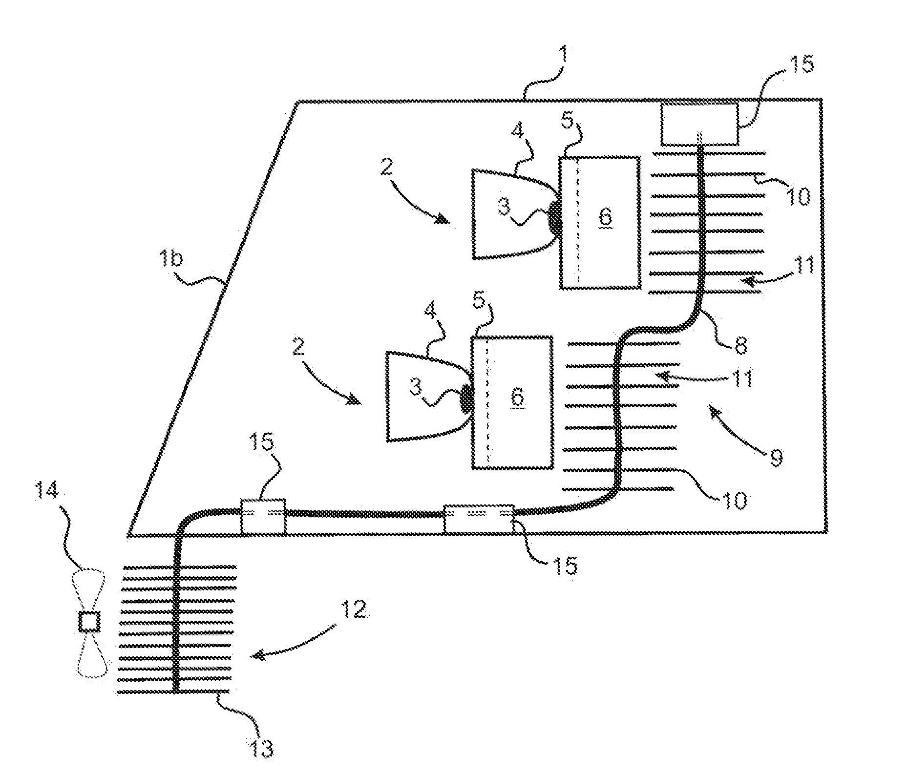
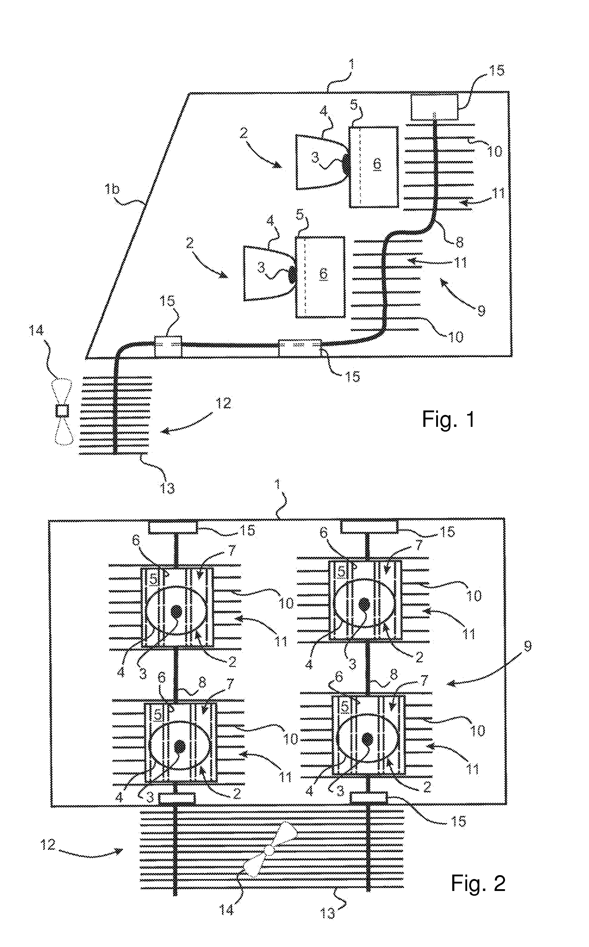
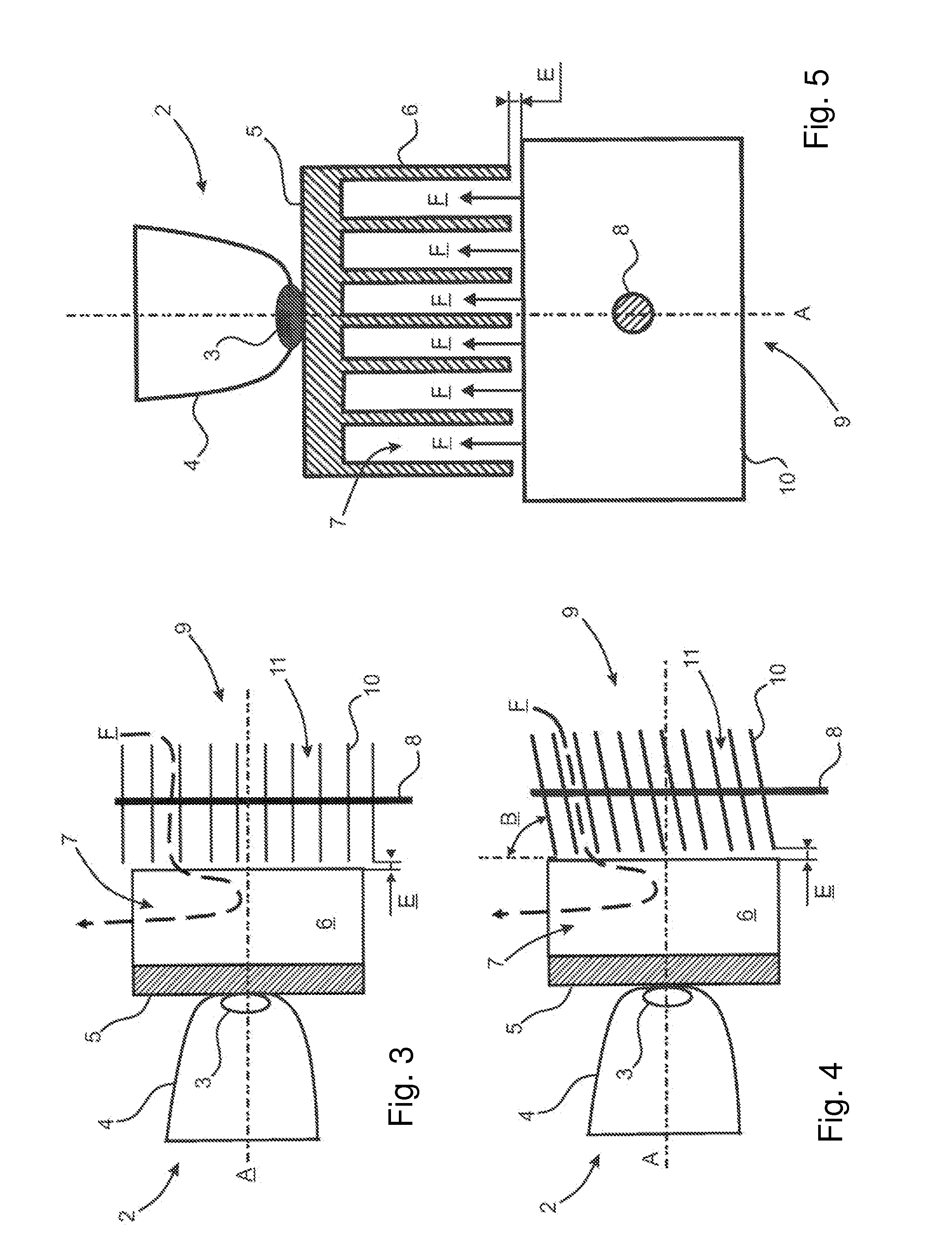
[0045]In FIGS. 1 and 2, a headlight for a motor vehicle comprises a housing 1 which is closed by transparent closure glass 1b. The housing 1 accommodates a plurality of optical modules 2 for emission of at least one global light beam. These optical modules 2 associate a source of light 3 which is constituted by an LED and an optical system which can modify at least one of the parameters of the light which is generated by the source of light 3, such as its mean reflection and / or its direction. In the example represented, the optical system comprises a reflector 4, which concentrates the light emitted by the source of light 3 in the direction of the transparent closure glass 1b, i.e., towards the left in the diagram in FIG. 1. The optical modules 2 are supported by cooling units 5, which are designed to dissipate the heat which is generated by the source of light 3 in operation. The cooling units 5 consist of a heat dissipater with fins, the fins 6 constituting a global surface of hea...


PUM


Abstract

A lighting and/or signaling device comprising at least one optical module equipped with a cooling unit, comprising at least one heat conductor, one end of which is placed spaced from the cooling unit, and is provided with a plurality of deflectors which channel a flow of cold air towards a heat-exchange surface of the cooling unit.

Description

CROSS-REFERENCE TO RELATED APPLICATIONS[0001]This application claims priority to French Application No. 0807166 filed Dec. 18, 2008, which application is incorporated herein by reference and made a part hereof.BACKGROUND OF THE INVENTION[0002]1. Field of the Invention[0003]The invention relates to the field of lighting devices, and more particular to that of motor vehicle headlights. Its object is a device for cooling one or a plurality of optical modules which equip a headlight of this type, for emission of various light beams. More specifically, this cooling device is of the type which induces heat exchange by convection between this flow of air and the heat-exchange surface of a cooling unit, such as a heat dissipater with fins or the like, which equips the optical module(s).[0004]2. Description of the Related Art[0005]In general, motor vehicle headlights consist of a housing which is closed by a transparent wall, through which one or a plurality of light beams are emitted. This ...

Claims


Application Information

Patent Timeline
Patent Type & Authority Applications(United States)
IPC IPC(8): F21V29/00F21W107/10
CPCF21S48/115F21S48/328F21V29/006F21Y2101/02F21V29/85F21V29/745F21V29/76F21V29/763F21V29/83F21V29/717F28D15/0275F21V29/51F21V29/67F21Y2115/10F21S41/143F21S41/153F21S43/14F21S45/43F21S45/48
Inventor ROUCOULES, CHRISTINEMORNET, ERIC
Owner VALEO VISION SA
Why Eureka
Try Eureka