Anti-rotation drive mechanism for a reciprocating saw

a technology of anti-rotation and drive mechanism, which is applied in the direction of oblique crank gearing, portable drilling machine, machining, etc., can solve the problem of non-circular cross-section increasing the cos

Active Publication Date: 2005-12-01
CREDO TECH CORP +1
View PDF11 Cites 32 Cited by
  • Summary
  • Abstract
  • Description
  • Claims
  • Application Information

AI Technical Summary

Benefits of technology

[0004] A preferred embodiment of the present invention is directed to an anti-rotation reciprocating drive apparatus for a reciprocating saw that utilizes a wobble plate assembly that includes a drive shaft and an elongated arm with an interface structure for engaging a spindle. The interface structure has two ball-type interfaces that are concentrically aligned with one another, with the outer one being smaller than the inner one and both engaging a receiver portion of the spindle. The larger ball-type interface causes reciprocating movement of the spindle and the smaller outer interface prevents rotation of the spindle. The contact between the interfaces and the spindle receiver is a single point contact which reduces operating friction, wear of the parts and heat being generated.

Problems solved by technology

While these noncircular cross-section spindles operate in a desirable manner, the noncircular cross-section increases the cost relative to a tubular spindle construction which is more desirable.
However, a tendency of wobble plate drives for driving a spindle is to exert forces on the spindle which tend to cause it to rotate.

Method used


Image

  • Anti-rotation drive mechanism for a reciprocating saw
  • Anti-rotation drive mechanism for a reciprocating saw
  • Anti-rotation drive mechanism for a reciprocating saw

Examples


Embodiment Construction

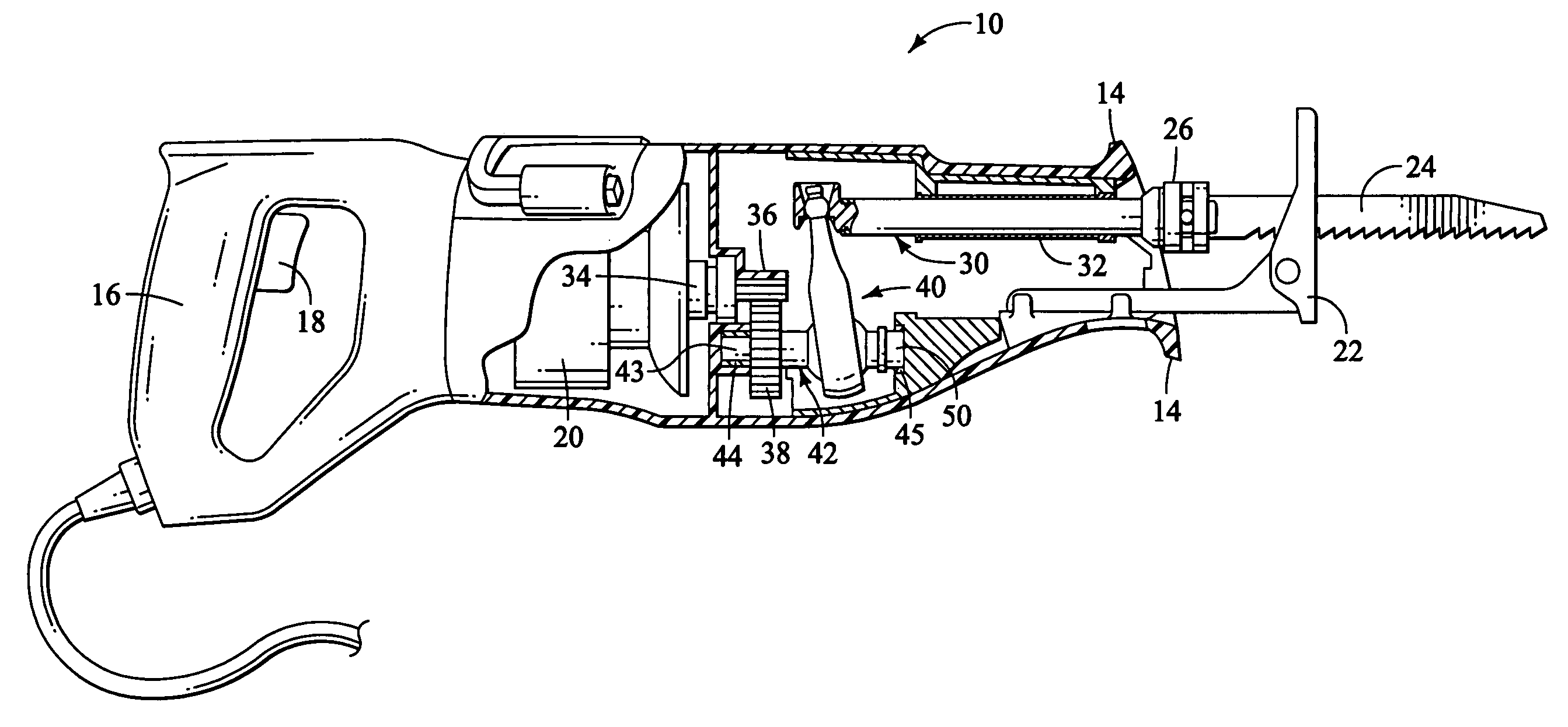
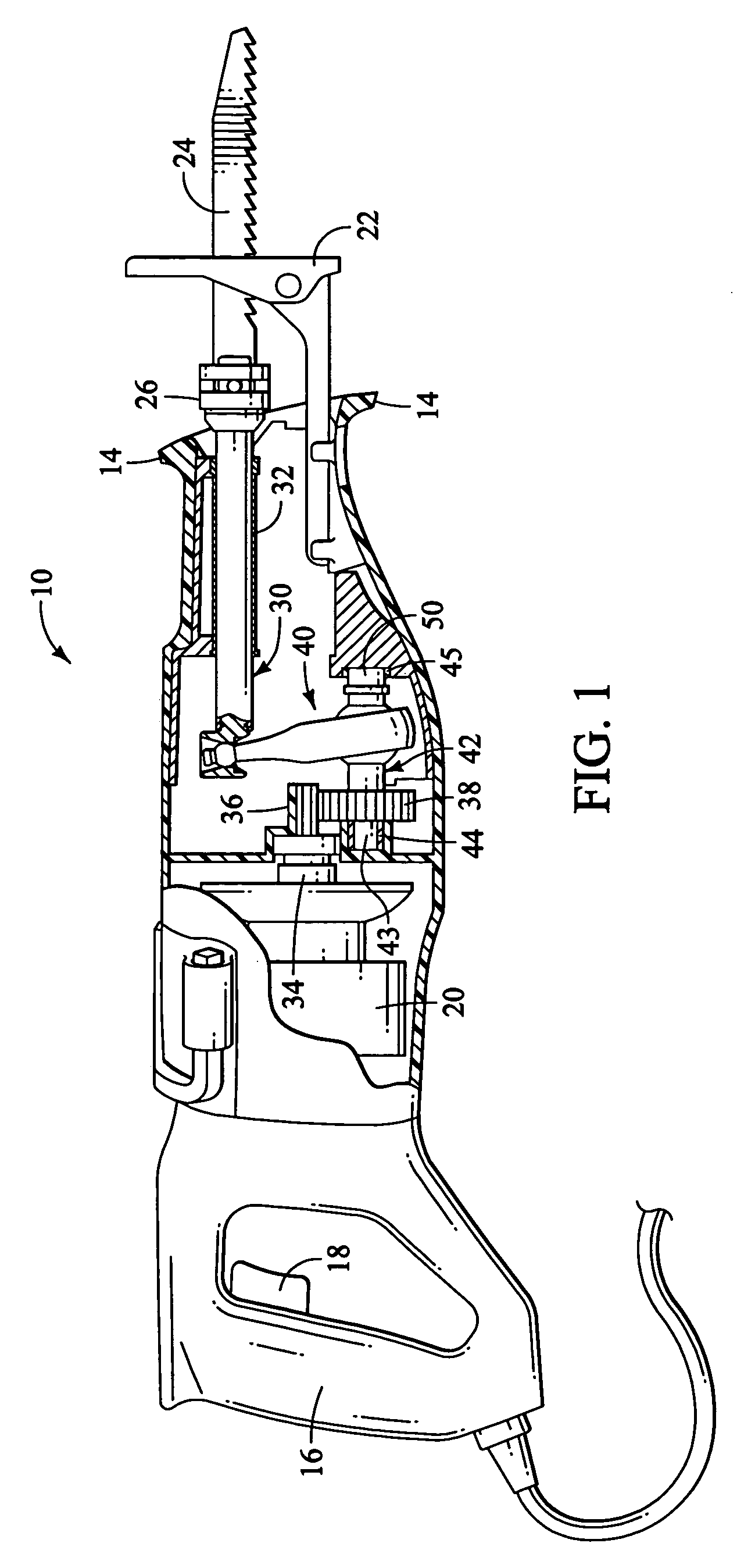
[0015] The preferred embodiment of the present invention is shown in the drawings and is a reciprocating saw, the general size and shape of which is similar to saws that are currently marketed. The present invention is also adapted for other types of tools such as saber saws, for example, or other types of tools that have a reciprocating action and are powered by a motor having a rotating output shaft. As shown in FIG. 1, the reciprocating saw, indicated generally at 10, has an outer housing 12 which includes a nose portion 14 that is flared outwardly so that a user can hold the nose portion with one hand while holding a handle 16 with the other. A trigger switch 18 is provided in the handle portion for turning on a motor 20 that drives the tool. The saw has a shoe 22 at the nose end portion 14 and a saw blade 24 is mounted in a blade clamping mechanism 26 that is mounted at the end of an elongated spindle and receiver, indicated generally at 30, which is slideable in a hollow cylin...


PUM

PropertyMeasurementUnit
circumferenceaaaaaaaaaa
lengthaaaaaaaaaa
diameteraaaaaaaaaa

Abstract

An anti-rotation reciprocating drive apparatus for a reciprocating saw utilizes a wobble plate assembly that includes a drive shaft and an elongated arm with an interface structure for engaging a spindle. The interface structure has two ball-type interfaces that are concentrically aligned with one another, with the outer one being smaller than the inner one and both engaging a receiver portion of the spindle. The larger ball-type interface causes reciprocating movement of the spindle and the smaller outer interface prevents rotation of the spindle. The contact between the interfaces and the spindle receiver is a single point contact which reduces operating friction, wear of the parts and heat being generated.

Description

BACKGROUND OF THE INVENTION [0001] The present invention generally relates to hand tools, and more particularly, to power reciprocating hand tools. [0002] Reciprocating tools that are motor driven, such as saber saws, larger reciprocating saws and the like are usually driven by electric motors that have a rotating output shaft. Therefore, this rotating motion must be translated into reciprocating motion for moving a saw blade or the like in a reciprocating manner. While various types of mechanisms have been known in the art for translating the rotation motion into reciprocating motion, one common type of motion conversation mechanisms are wobble plate drives. A wobble plate drive shaft is typically connected to the motor through a gear arrangement that usually functions to reduce the speed of rotation of the motor output shaft and the wobble plate drive causes a wobble arm to reciprocate in a path that is parallel to the motion of the saw blade or the like which the wobble plate dri...

Claims


Application Information

Patent Timeline
Patent Type & Authority Applications(United States)
IPC IPC(8): B23D51/16B23Q5/027B27B19/00
CPCY10T74/18336B23D51/16B23D49/16B27B19/09
Inventor MORENO, JAIME
Owner CREDO TECH CORP
Why Eureka
Try Eureka