
Tall building escape apparatus

a technology for building escape and building walls, applied in building aids, safety belts, constructions, etc., can solve the problems of poor safety, slow escape speed, limitation of applicable height, etc., and achieve the effect of enhancing safety and speeding up escape speed

Inactive Publication Date: 2005-12-08
CHEN TZU I
View PDF11 Cites 10 Cited by
  • Summary
  • Abstract
  • Description
  • Claims
  • Application Information

AI Technical Summary

Benefits of technology

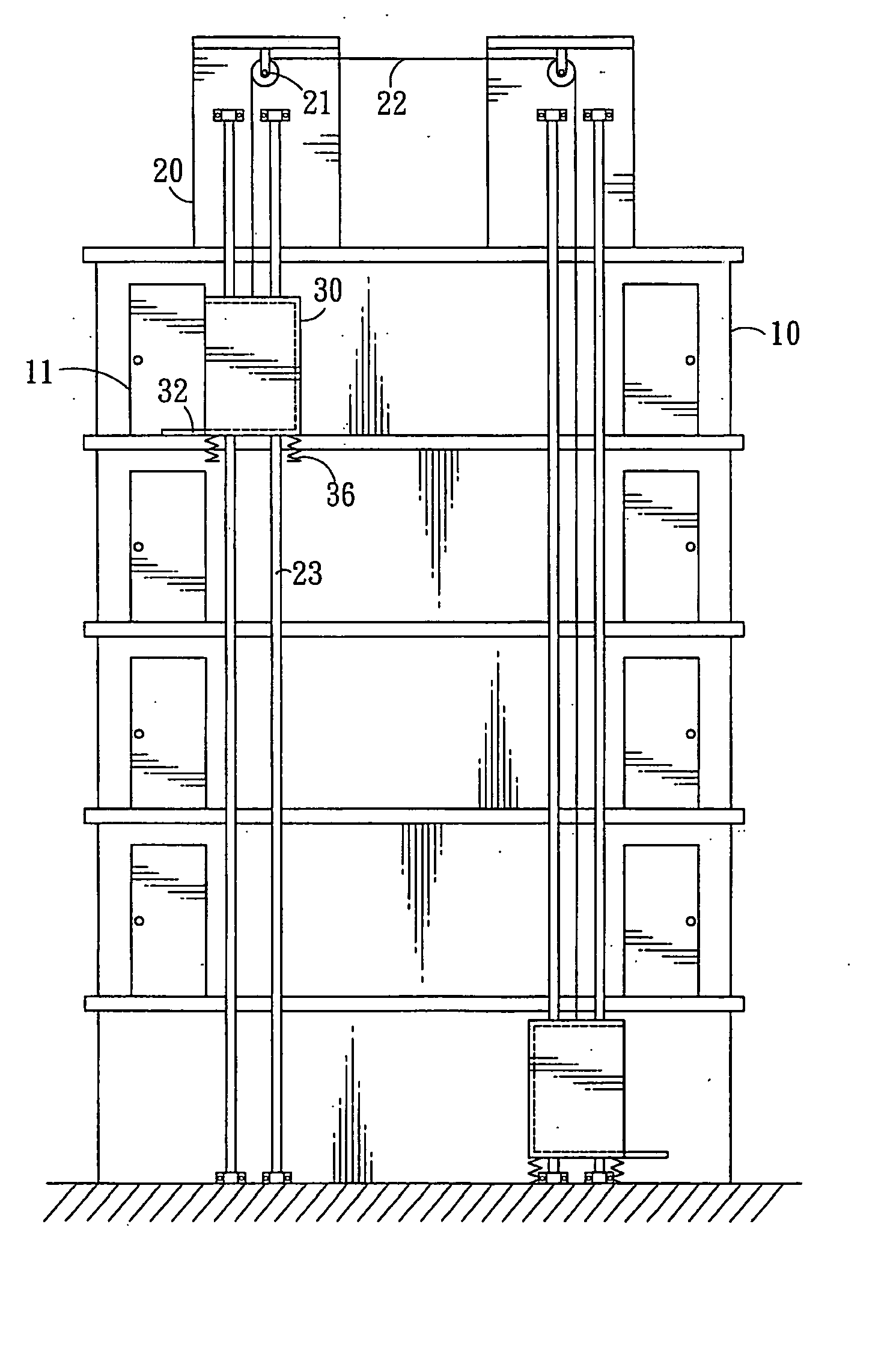
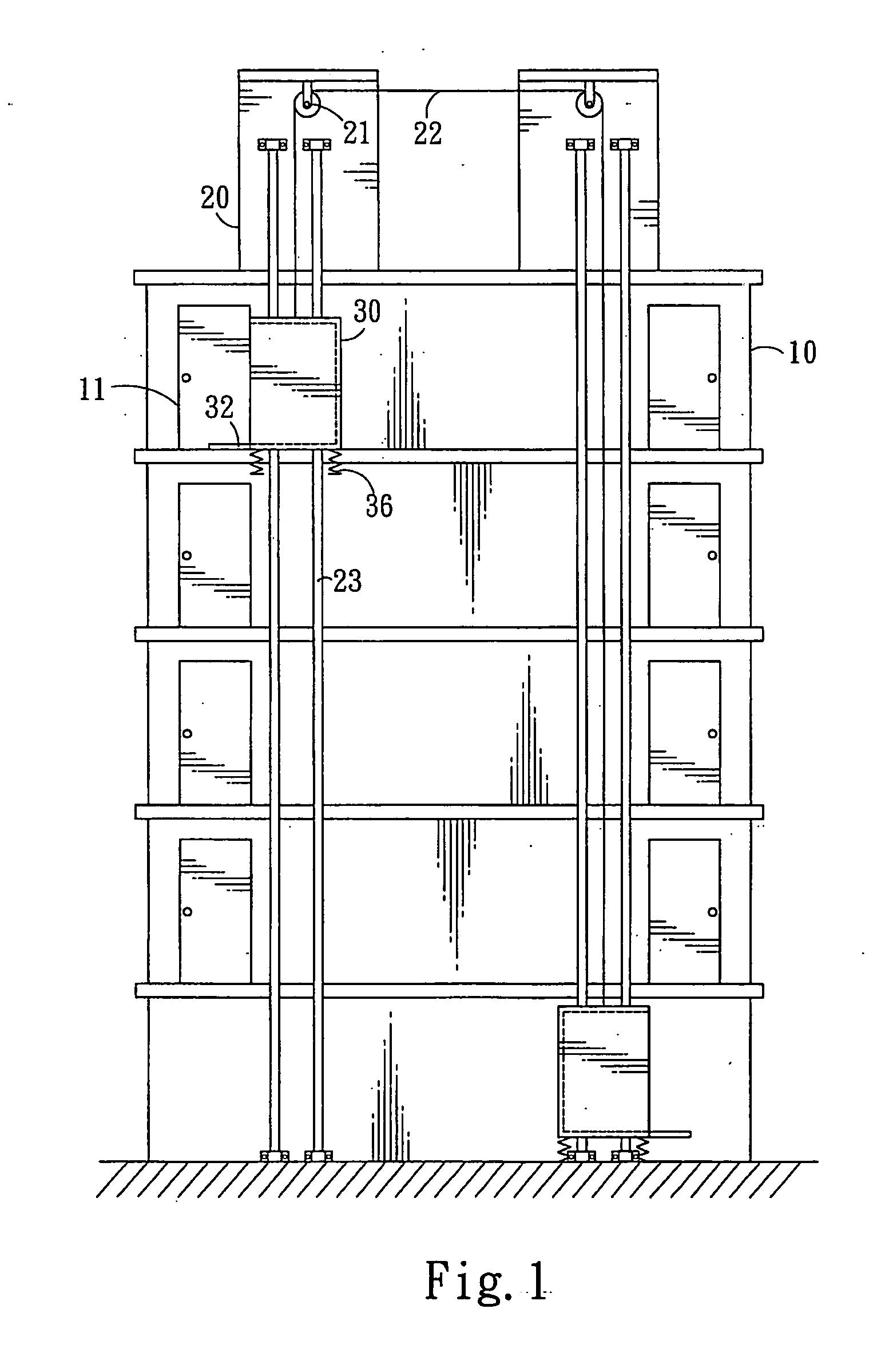
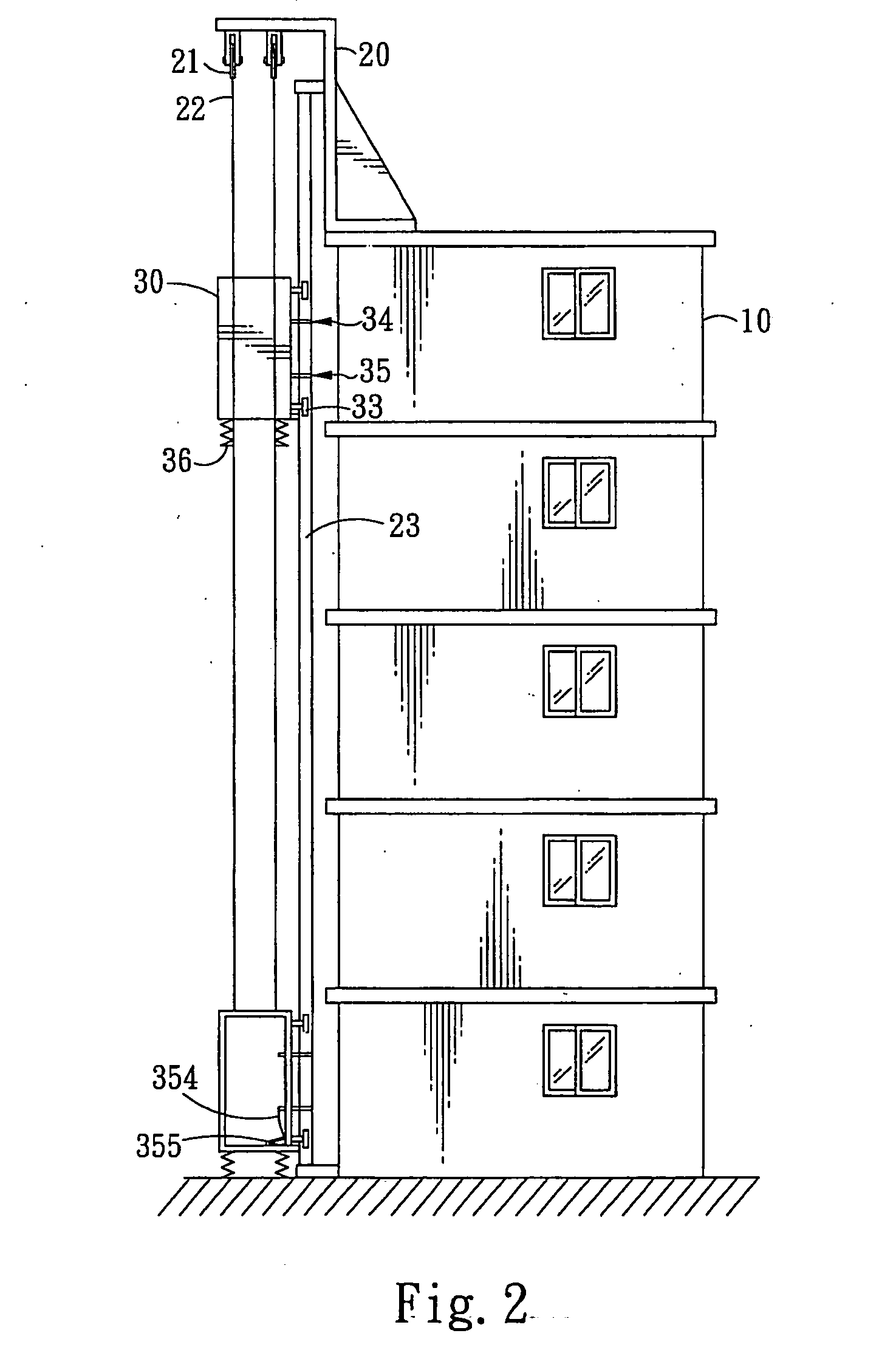
[0010] In view of the aforesaid disadvantages, the invention aims to provide a tall building escape apparatus that can provide rapid escape without using power equipment. The escape apparatus according to the invention includes two escape exits on one side of a building and two upright sliding rails abutting the escape exits. The sliding rails are cylindrical rods extended from the ground floor to the top floor of the building. There are hanging racks on the top floor corresponding to the sliding rails. There are pulleys fixedly mounted on the hanging racks to wind a rope. The rope has two ends each is fastened to an escape case. The escape case has retaining wheels that have a curved periphery to clamp the sliding rail. The bottom side of the escape case has buffer members. There is an entrance / exit opening located on one side of the escape case directing to the escape exit. When a user descends through one escape case, another escape case is lifted by the rope at the same time to enable another user to escape. Thus not only escape speed is faster, safety is enhanced, and there is not applicable height limitation.
[0011] By means of the structure set forth above, the invention can provide the following advantages:
[0013] As there are two sets of pulleys located on the top floor of the building to wind the rope, and two escape cases are fastened to two ends of the rope, when one escape case is descended to convey an user, the rope pulls another escape case upwards at the same time to enable another user to escape. There is no waiting or waste of time.
[0015] The escape case slides downwards along the sliding rails, and the bottom side of the escape case has buffer members to provide cushion so that users may be prevented from injury when the escape case drops to the ground floor.
[0017] The two escape cases are linked by the rope and slide along the sliding rails, hence they may be used securely without height limitation. Moreover, descending and lifting of the escape cases are steadier.

Problems solved by technology

However such a slow descending apparatus has drawbacks, such as the escape speed is slow, poor safety, and has limitation on the applicable height.
Not only the descending speed is slow, the winding of the loop strap is a waste of time.
Poor safety: During descending, the user is hitched by the loop strap and hanged in a suspended manner in the air without any traction in the surrounding.
The user tends to dangle or swivel under external forces.

Method used


Image

  • Tall building escape apparatus
  • Tall building escape apparatus
  • Tall building escape apparatus

Examples


Embodiment Construction

[0025] Please referring to FIGS. 1, 2 and 3, the tall building escape apparatus according to the invention includes at least two escape exits on each floor of a building 10 that may be escape doors 11, or escape windows or balconies. The drawings show the escape doors 11 as an example. On one side of the escape door 11, there are two upright and parallel sliding rails 23 that are extended from the ground floor to the top floor of the building 10. The sliding rails 23 are cylindrical rods. The top floor of the building 10 has two hanging racks 20 on the edge corresponding to the sliding rails 23 that are extended outside the edge of the building 10. The bottom side of the hanging rack has two pulleys 21 fastened thereon in a front and a rear manner. The pulleys 21 at the front side are wound by a rope 22. The pulleys 21 at the rear side also are wound by another rope 22. The rope 22 winds the pulleys 21 at least one time. The rope 22 has two ends fastened respectively the two escape ...


PUM


Abstract

A tall building escape apparatus includes two upright sliding rails on one side of a building where two escape exits are located. The sliding rails are cylindrical rods extended from the ground floor to the top floor of the building corresponding to hanging racks located on the top floor. The hanging racks have pulleys mounted thereon to wind a rope between the two hanging racks. The rope has two ends fastened respectively to an escape case. The escape case has retaining rollers with curved periphery to clamp the sliding rails, buffer members on the bottom side, and an entrance / exit opening on one side directing to the escape exit. When a user escapes by descending through one escape case, another escape case is pulled by the rope upwards to enable another user to escape. Thus escape speed is faster, and safety is enhanced and there is no limitation of the applicable height.

Description

FIELD OF THE INVENTION [0001] The present invention relates to a tall building escape apparatus and particularly to an escape apparatus to provide rapid escape without using power equipment. BACKGROUND OF THE INVENTION [0002] Public building has to provide fire fighting and escape facilities. The most commonly used escape facility is the slow descending apparatus which includes a hanging rack fixedly installed on each floor of the building and a slow descending device located nearby. In the event of fire breaking, the slow descending device is hung on the hanging rack, and a loop strap of the slow descending, device is hitched on the user. The user may descend slowly to the ground floor by means of user's own weight from the high rise building. [0003] However such a slow descending apparatus has drawbacks, such as the escape speed is slow, poor safety, and has limitation on the applicable height. Details of these drawbacks are elaborated as follow: [0004] 1. Slow escape speed: [0005...

Claims


Application Information

Patent Timeline
Patent Type & Authority Applications(United States)
IPC IPC(8): A62B1/02E04G3/00
CPCA62B35/0062A62B1/02
Inventor CHEN, TZU-I
Owner CHEN TZU I
Learn More