Post puller

a post puller and pulley technology, applied in the direction of lifting devices, building types, constructions, etc., can solve the problems of inability to support the system, tractors and front loaders require the presence of this very expensive piece of equipment, and are generally heavy, complicated, and expensive, and achieves easy release, tight gripping, and rapid

Inactive Publication Date: 2005-12-15
NELSON MARK STEPHEN
View PDF0 Cites 50 Cited by
  • Summary
  • Abstract
  • Description
  • Claims
  • Application Information

AI Technical Summary

Problems solved by technology

The disadvantage of the lever systems is that the lever fulcrum is laterally distant from the center of the piece to be extracted, which is an unstable system.
The machines attached to such things as tractors and front loaders require the presence of this very expensive piece of equipment.
Most hydraulic systems are also supported laterally distant from the extraction center and are generally heavy, complicated, and expensive.
A post puller in U.S. Pat. No. 6,389,188 to Salman, 2002 Jun. 4, has a center of extraction directly over the post however it is hydraulic, complicated, heavy, and lacks compactness.
A post puller in U.S. Pat. No. 6,382,594 B1 to Ransom, 2002 May 7, is an extremely complicated hydraulic machine that lacks compactness, light weight, and low cost of construction.

Method used


Image

  • Post puller
  • Post puller
  • Post puller

Examples


Embodiment Construction

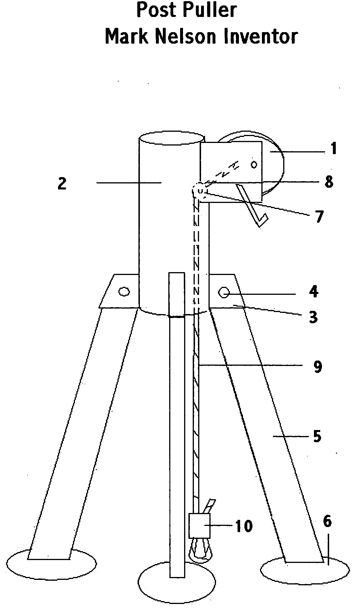
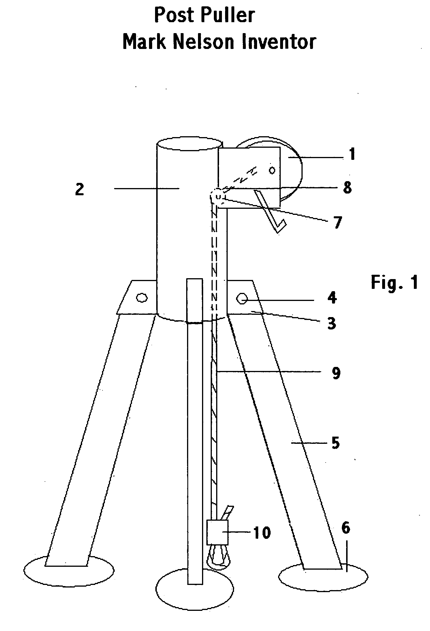
FIG. 1—Preferred Embodiment.

[0042] A preferred embodiment of the present invention is illustrated in FIG. 1.

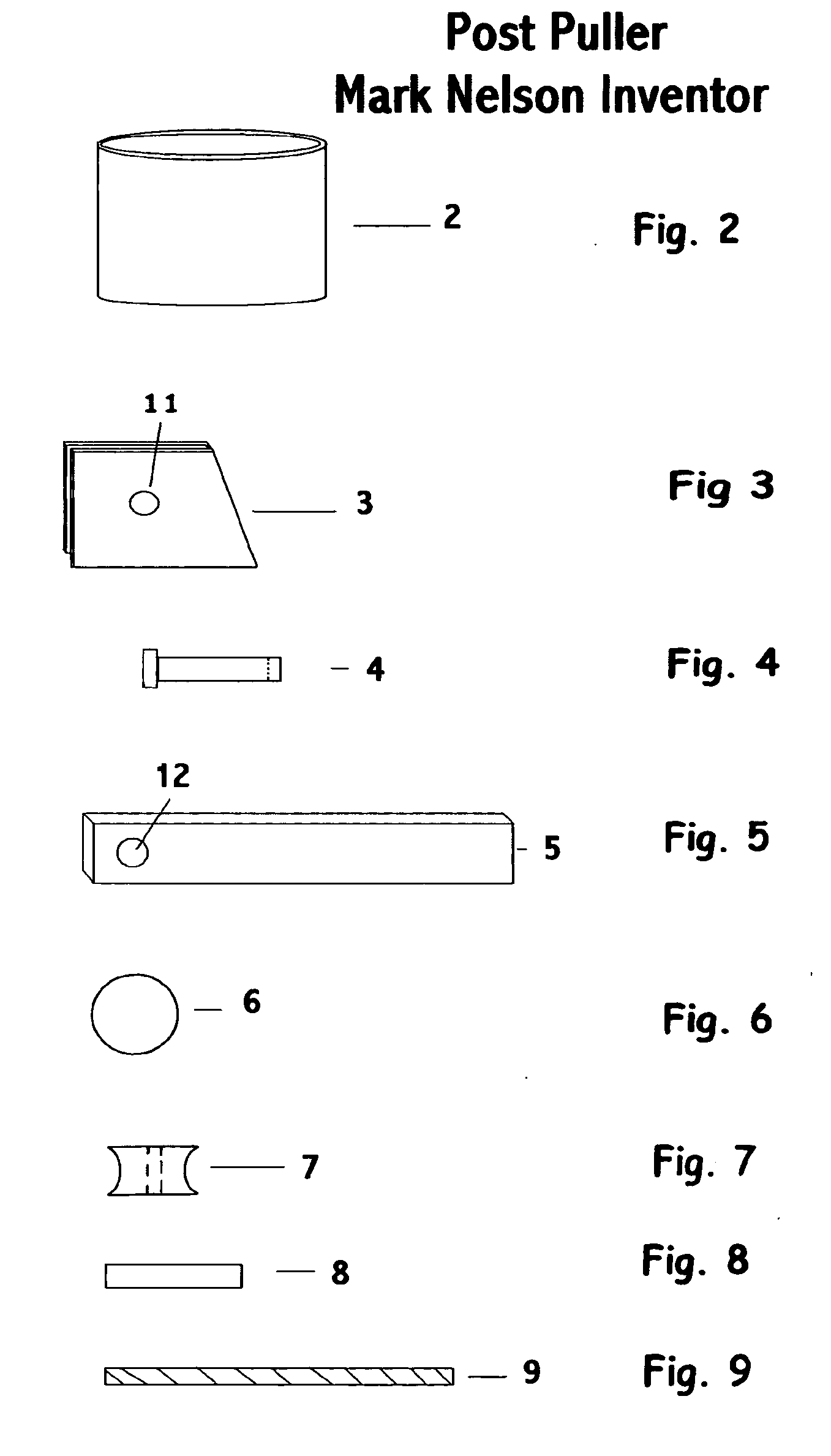
[0043] A body 2 as shown in FIGS. 1 and 2 may be produced from a group of materials consisting of steel (preferred), aluminum, titanium, or other material of suitable tensile and yield strength to accommodate the stresses of the a particular object to be extracted.

[0044] Onto the body 2 are attached 3 brackets 3 as seen in FIGS. 1 and 3 which can be produced from plate steel, aluminum, or other durable material and serve as support for a leg 5. A bracket hole 11 as seen in FIG. 3 is drilled in the top of the bracket and serves to facilitate attachment of the leg 5 to the bracket 3.

[0045] The leg 5 as seen in FIGS. 1 and 5 may be produced from tubular steel, pipe or any other material with adequate yield strength to support the object to be extracted. Into one end of the leg 5 is drilled a leg hole 12 as seen in FIG. 5 which allows the leg 5 to swivel inward for storage or o...


PUM

PropertyMeasurementUnit
weightaaaaaaaaaa
stabilityaaaaaaaaaa
durabilityaaaaaaaaaa

Abstract

A simple, stable, inexpensive, light weight, compact device that allows a single operator to vertically extract embedded objects such as fence posts. The device is placed over the object and a self tightening noose in the cable end is positioned around the object near the ground. A cable winch is then activated allowing for easy removal of the embedded object. After completion of the operation, the winch tension is released, the cable removed from the object, and the operator is free to begin the next operation.

Description

CROSS-REFERENCE TO RELATED APPLICATIONS [0001] Not applicable STATEMENT REGARDING FEDERALLY SPONSORED RESEARCH OR DEVELOPMENT [0002] This invention was not conceived or produced with the aid of any federally sponsored research or development. BACKGROUND OF THE INVENTION [0003] 1. Field of the Invention [0004] This invention relates to an extraction device, specifically a tripod based, compact, light weight, cable winch powered device for removing objects embedded in the ground. [0005] 2. Description of Prior Art [0006] Currently patented devices used for extracting posts have included such things as a simple lever type apparatus, complicated machines that must be attached to heavy equipment, and hydraulically powered systems. The disadvantage of the lever systems is that the lever fulcrum is laterally distant from the center of the piece to be extracted, which is an unstable system. The machines attached to such things as tractors and front loaders require the presence of this very ...

Claims


Application Information

Patent Timeline
Patent Type & Authority Applications(United States)
IPC IPC(8): E04H17/26B66F3/00
CPCE04H17/265
Inventor NELSON, MARK STEPHEN
Owner NELSON MARK STEPHEN
Why Eureka
Try Eureka