Mechanical layout and component placement for thin clamshell phone

a technology of mechanical layout and component placement, applied in the direction of telephone set construction, substation equipment, electrical equipment, etc., can solve the problems of increased components and/or circuit elements, reduced size, and device may become difficult to opera

Inactive Publication Date: 2005-12-22
GOOGLE TECH HLDG LLC
View PDF10 Cites 52 Cited by
  • Summary
  • Abstract
  • Description
  • Claims
  • Application Information

AI Technical Summary

Problems solved by technology

Adding more functionality often leads to increased components and / or circuit elements, which often correspond to increased space requirements, which is at odds with the desire to make devices smaller.
For example, while smaller is generally thought to be better in connection with overall size, size reduction can be limited by usage requirements, where if certain components of a device, such as the keypad, are allowed to shrink too much, the device may become difficult to operate.
While this is a valid approach for reducing the overall depth, at any given time, there may be limits as to how far the depth of a particular component may be reduced.

Method used


Image

  • Mechanical layout and component placement for thin clamshell phone
  • Mechanical layout and component placement for thin clamshell phone
  • Mechanical layout and component placement for thin clamshell phone

Examples


Embodiment Construction

[0015] As required, detailed embodiments of the present invention are disclosed herein; however, it is to be understood that the disclosed embodiments are merely exemplary of the invention, which can be embodied in various forms. Therefore, specific structural and functional details disclosed herein are not to be interpreted as limiting, but merely as a basis for the claims and as a representative basis for teaching one skilled in the art to variously employ the present invention in virtually any appropriately detailed structure. Further, the terms and phrases used herein are not intended to be limiting; but rather, to provide an understandable description of the invention.

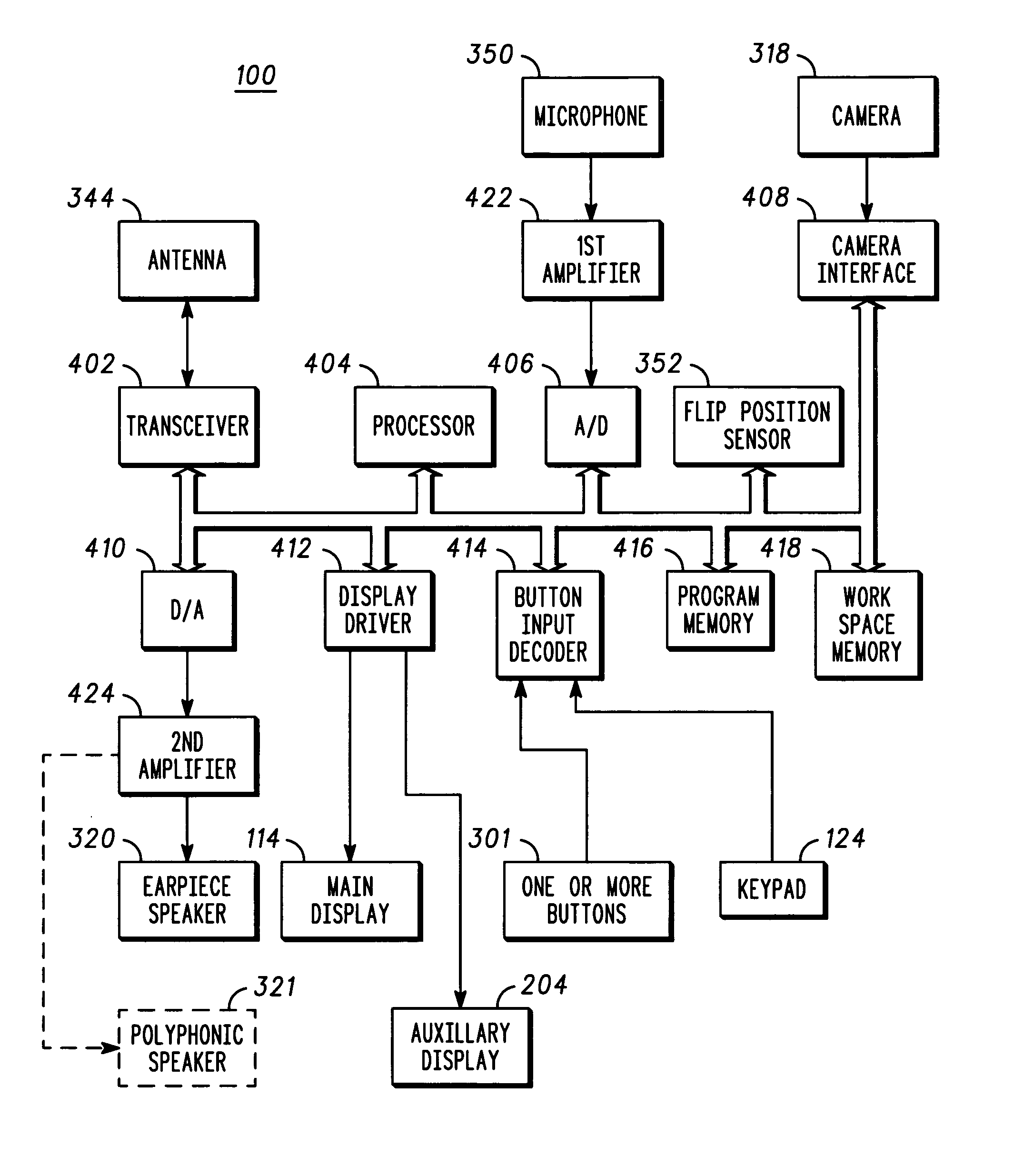
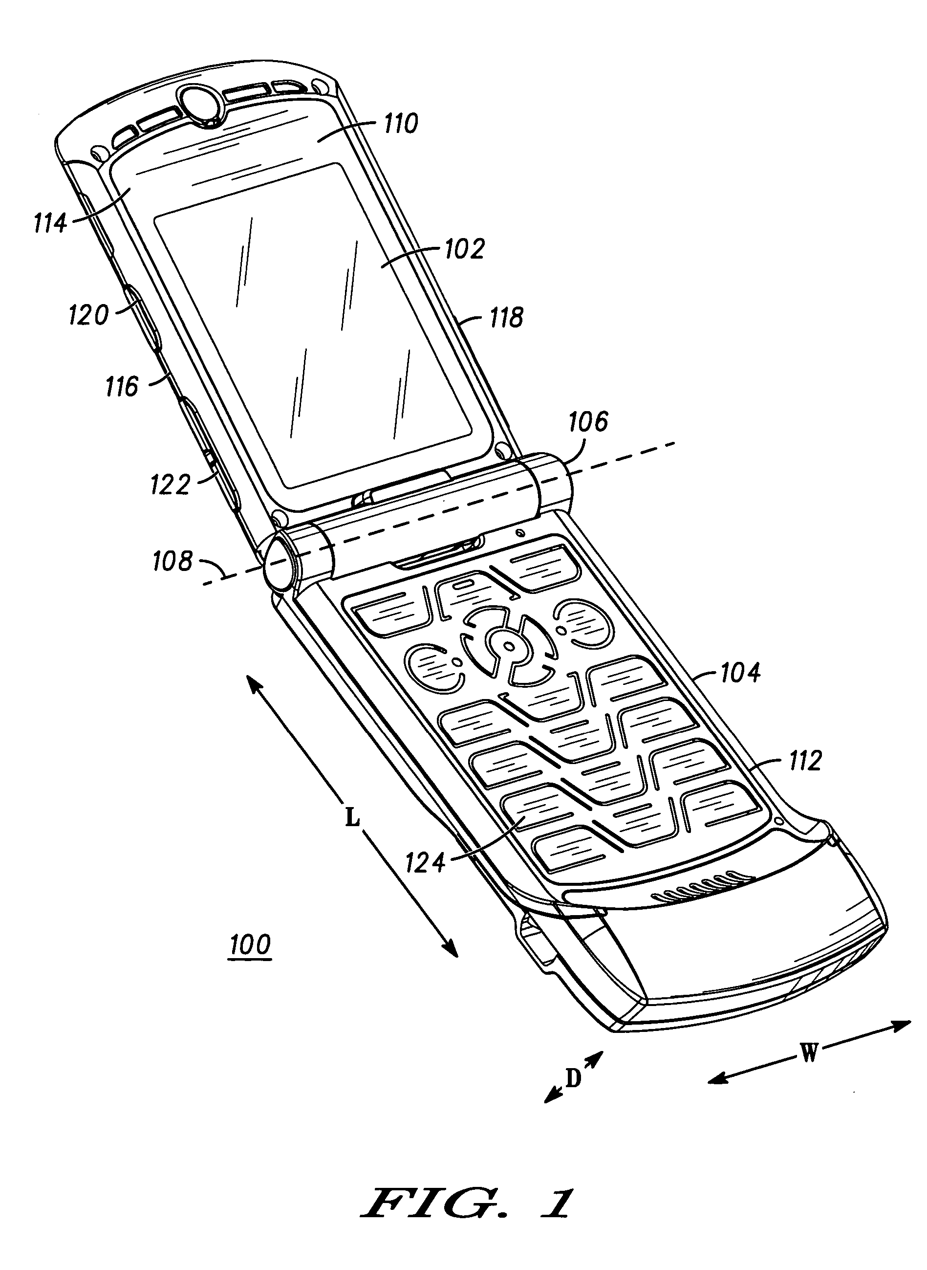
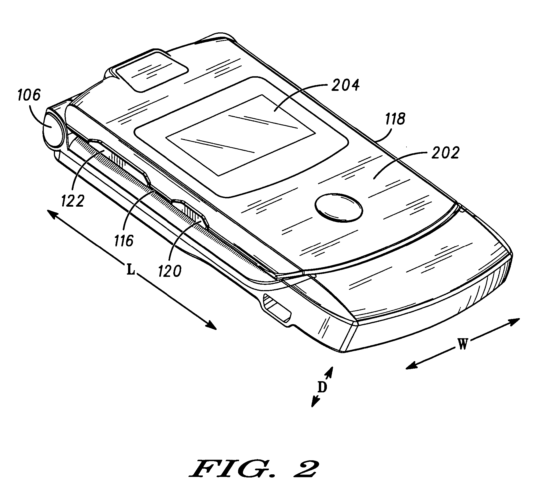
[0016]FIG. 1 is a first perspective view of a first handheld communication device, in particular a clamshell wireless communication device 100, shown in a first configuration and FIG. 2 is a second perspective view of the first handheld communication device 100, shown in a second configuration. The device 100 com...


PUM


Abstract

Folding wireless communication devices incorporate a two-part housing, which includes a first part that is rotatably coupled to a second part. The overall depth of the device is reduced by adjusting the mechanical layout and component placement relative to one another, wherein previously stacked components have been reordered. More specifically, the hinge, the battery, and the communication and control circuitry have been organized so as to be in the same horizontal plane, and so as to not overlap in a vertical direction.

Description

FIELD OF THE INVENTION [0001] The present invention relates in general to handheld communication devices. More particularly, the present invention relates to the mechanical layout and component placement for thin handheld communication devices, which have at least a two part housing, where the first housing part is adapted to rotate relative to the second housing part. BACKGROUND OF THE INVENTION [0002] There is an interest in making certain handheld electronic devices such as cellular telephones smaller. Making such devices smaller makes it more convenient to carry them around at all times. [0003] Concurrently there is a trend toward increasing the functionality of devices. In the case of cellular telephones, increased functionality includes providing operability on multiple frequency bands using multiple protocols and providing the ability to take and playback photographs and / or video clips. Adding more functionality often leads to increased components and / or circuit elements, whi...

Claims


Application Information

Patent Timeline
Patent Type & Authority Applications(United States)
IPC IPC(8): H04M1/02H04M1/73
CPCH04M1/0214H04M1/0277H04M1/0262H04M1/0245H04B1/38
Inventor SPENCE, MICHAEL F.ALLORE, JOSEPH L.DABBECKEH, JOHN H.JELLICOE, ROGER J.STONE, FRANK H.VOLLMER, SIMON F.WEISS, GARY R.
Owner GOOGLE TECH HLDG LLC
Why Eureka
Try Eureka