Outdoor umbrella structre concurrently having illumination and decoration functions

a technology of umbrellas and umbrellas, applied in the field of umbrellas, can solve problems such as the risk of electric leakage, and achieve the effects of safe, convenient and power-saving effects, and artistic effects

Inactive Publication Date: 2006-01-12
CHANG MING CHE
View PDF5 Cites 59 Cited by
  • Summary
  • Abstract
  • Description
  • Claims
  • Application Information

AI Technical Summary

Benefits of technology

[0005] The primary objective of this invention is to provide an outdoor umbrella structure concurrently having illumination and decoration functions, wherein a direct current battery is installed into the top of an upper tier; an electric wire at the bottom of the battery is electrically connected to an illuminating member; both ends of the illuminating member are pivotally coupled to the umbrella top r...

Problems solved by technology

However, if such umbrella is used outdoors, it is necessary to bring the power supply with you all the time.
Further, the electric wir...

Method used


Image

  • Outdoor umbrella structre concurrently having illumination and decoration functions
  • Outdoor umbrella structre concurrently having illumination and decoration functions
  • Outdoor umbrella structre concurrently having illumination and decoration functions

Examples


Embodiment Construction

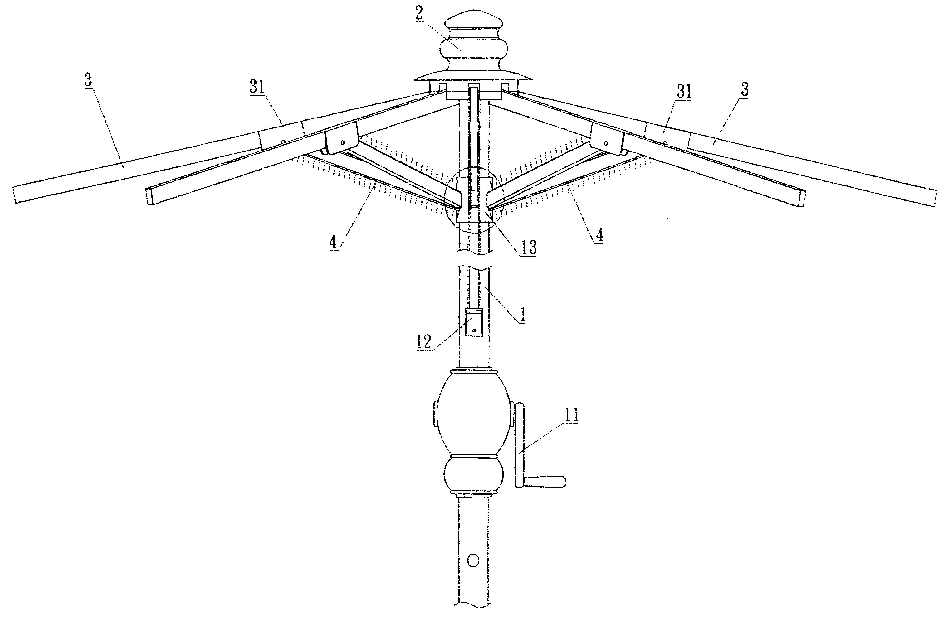
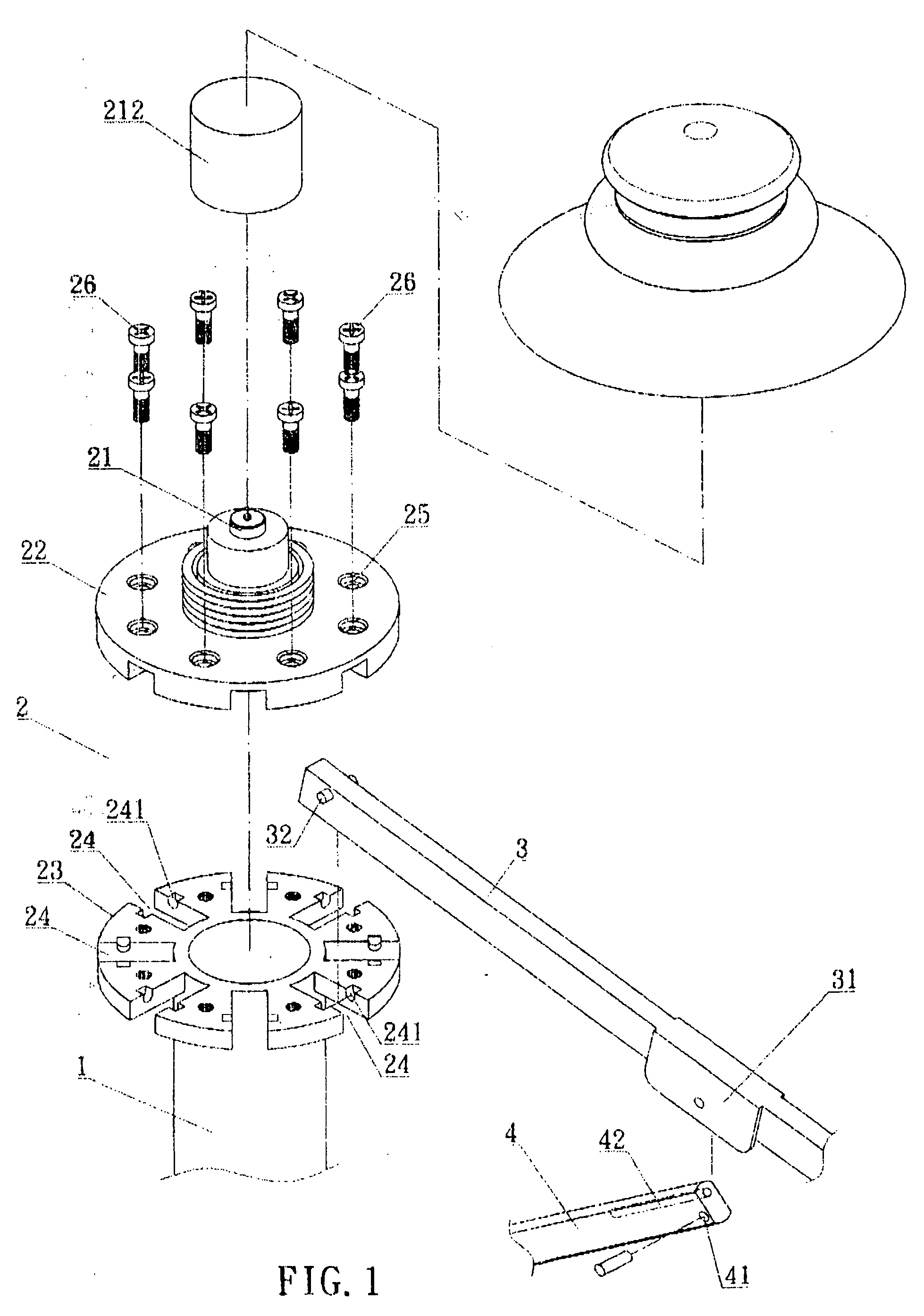
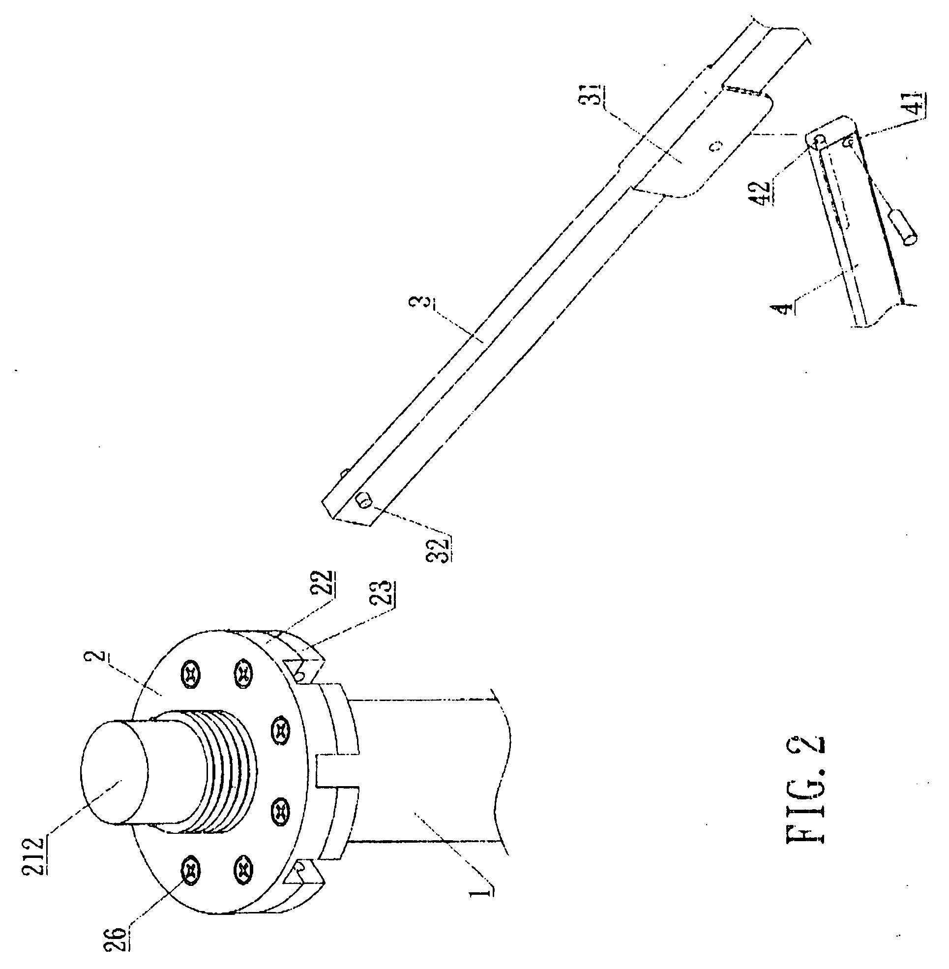
[0011] Please refer to FIGS. 1 to 4, it is obvious that the structure of the present invention comprises a support rod 1 erected from the center of an umbrella, an upper tier 2 disposed at the top of the support rod 1, a top umbrella rib extended outward from the upper tier 2 and an illuminating member 4 having one end pivotally coupled to the bottom of the top umbrella rib 3 and the other end pivotally coupled to a movable lower tier 5, wherein:

[0012] The support rod 1 comprises a manual-driven handle 11 at its bottom for pulling the movable lower tier 5 as to spread open or fold up the outdoor umbrella and a power switch disposed on the manual-driven handle 11 for controlling to turn on and off the light emitting diode LED inside the illuminating member 4.

[0013] The upper tier 2 is comprised of a pair of symmetric upper and lower decks 22, 23, and a symmetrically radiant groove 24 is disposed on the corresponding ends of the upper and lower decks for receiving an umbrella top ri...


PUM


Abstract

The present invention discloses an outdoor umbrella structure concurrently having illumination and decoration functions, which comprises a support rod vertically disposed at the center of the umbrella body, an upper tier disposed at the top end of the support rod, an umbrella top rib stretched outward from the upper tier, and an illuminating member having one end pivotally coupled to the umbrella top rib and the other end pivotally coupled to a movable lower tier; wherein a direct current battery is installed at the top of the upper tier and an electric cable extended from the bottom of the battery. Further, the front and rear ends of the illuminating member are pivotally coupled to the umbrella top rib and the lower movable tier respectively, and a light emitting diode is disposed in the illuminating member and emits the reflected light inside the illuminating member, and then focuses and projects the reflected light at the shaded area under the umbrella in order to make the illuminating member to have a pervious function. With a direct current battery, the present invention could be used in any place without much limitation. Since the reflected light in the illuminating member is focused and projected at the shaded area under the umbrella, the present invention can achieve the artistic, safe, convenient and power-saving effects.

Description

BACKGROUND OF THE INVENTION [0001] 1. Field of the Invention [0002] This invention relates to an umbrella, more particularly to an outdoor umbrella concurrently having illumination and decoration functions. [0003] 2. Description of the Related Art [0004] In general, the structure of a traditional outdoor umbrella fixes a lamp on an umbrella rib and electrically connects the lamp by alternate current. However, if such umbrella is used outdoors, it is necessary to bring the power supply with you all the time. Further, the electric wire is exposed under direct sunlight and rain and thus there is a risk of electric leakage when the insulating surface is damaged or loosened. SUMMARY OF THE INVENTION [0005] The primary objective of this invention is to provide an outdoor umbrella structure concurrently having illumination and decoration functions, wherein a direct current battery is installed into the top of an upper tier; an electric wire at the bottom of the battery is electrically conn...

Claims


Application Information

Patent Timeline
IPC IPC(8): A45B3/02
CPCA45B3/04
Inventor CHANG, MING-CHE
Owner CHANG MING CHE
Why Eureka
Try Eureka