Modular floor tile system with transition edge

a technology of floor tiles and transition edges, applied in resiliently-mounted floors, single-unit pavings, ways, etc., can solve the problems of difficult to move objects on rollers across the step and onto the floor tiles

Active Publication Date: 2006-01-26
SNAP LOCK INDS
View PDF60 Cites 37 Cited by
  • Summary
  • Abstract
  • Description
  • Claims
  • Application Information

AI Technical Summary

Problems solved by technology

For many purposes, however, the abrupt step presents a number of problems.
In addition, it can be difficult to move objects on rollers across the step and onto the floor tiles.

Method used


Image

  • Modular floor tile system with transition edge
  • Modular floor tile system with transition edge
  • Modular floor tile system with transition edge

Examples


Embodiment Construction

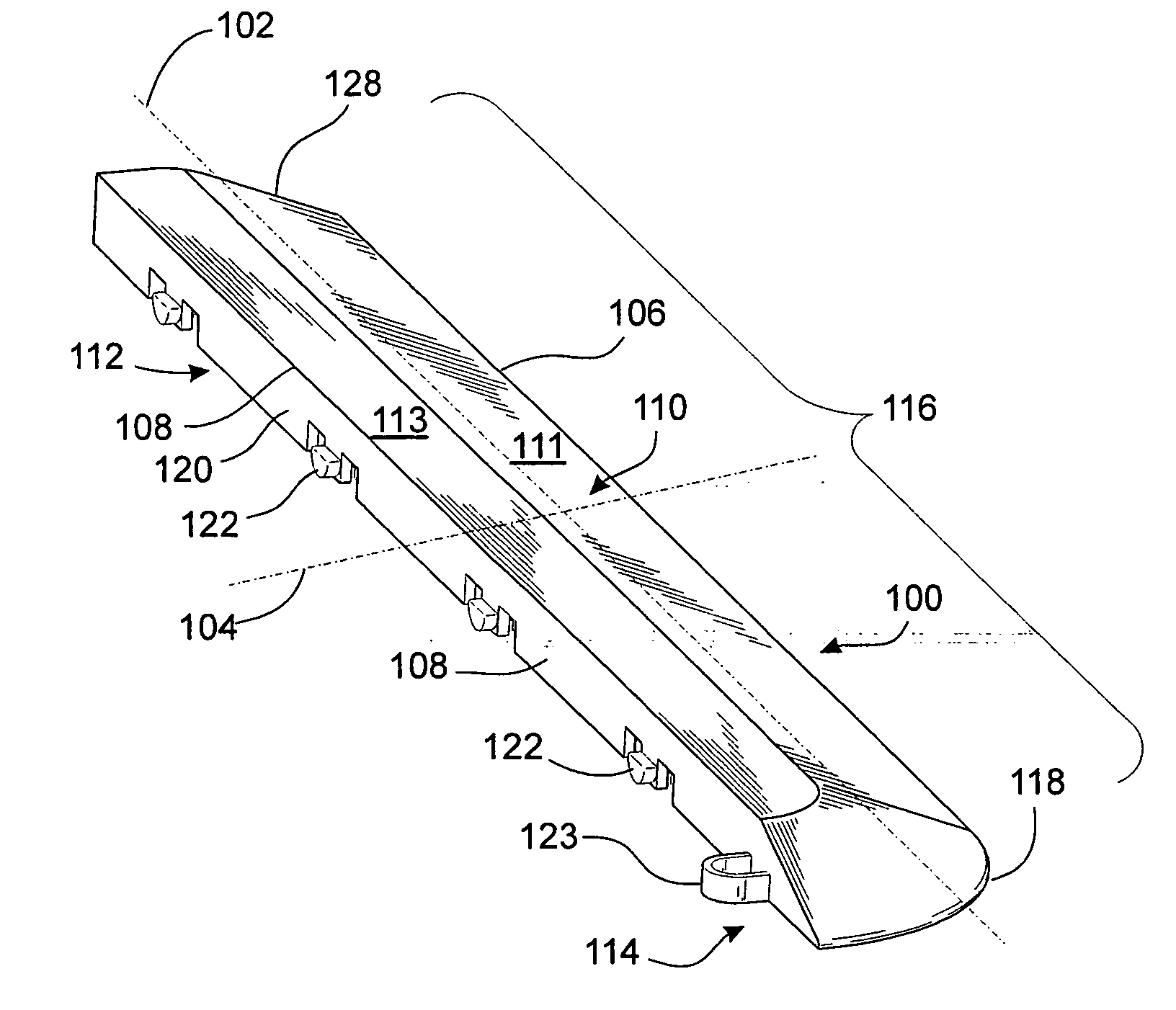
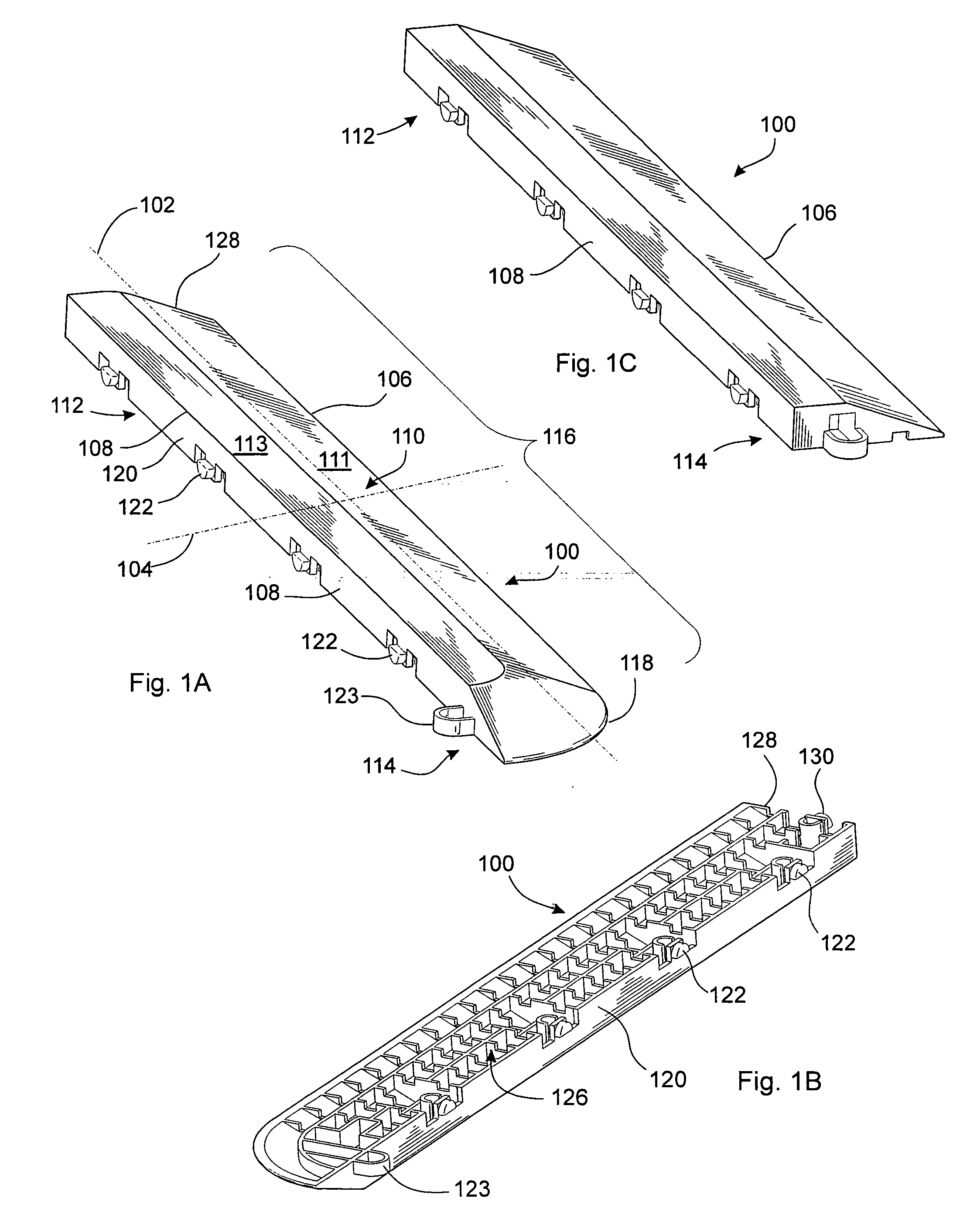
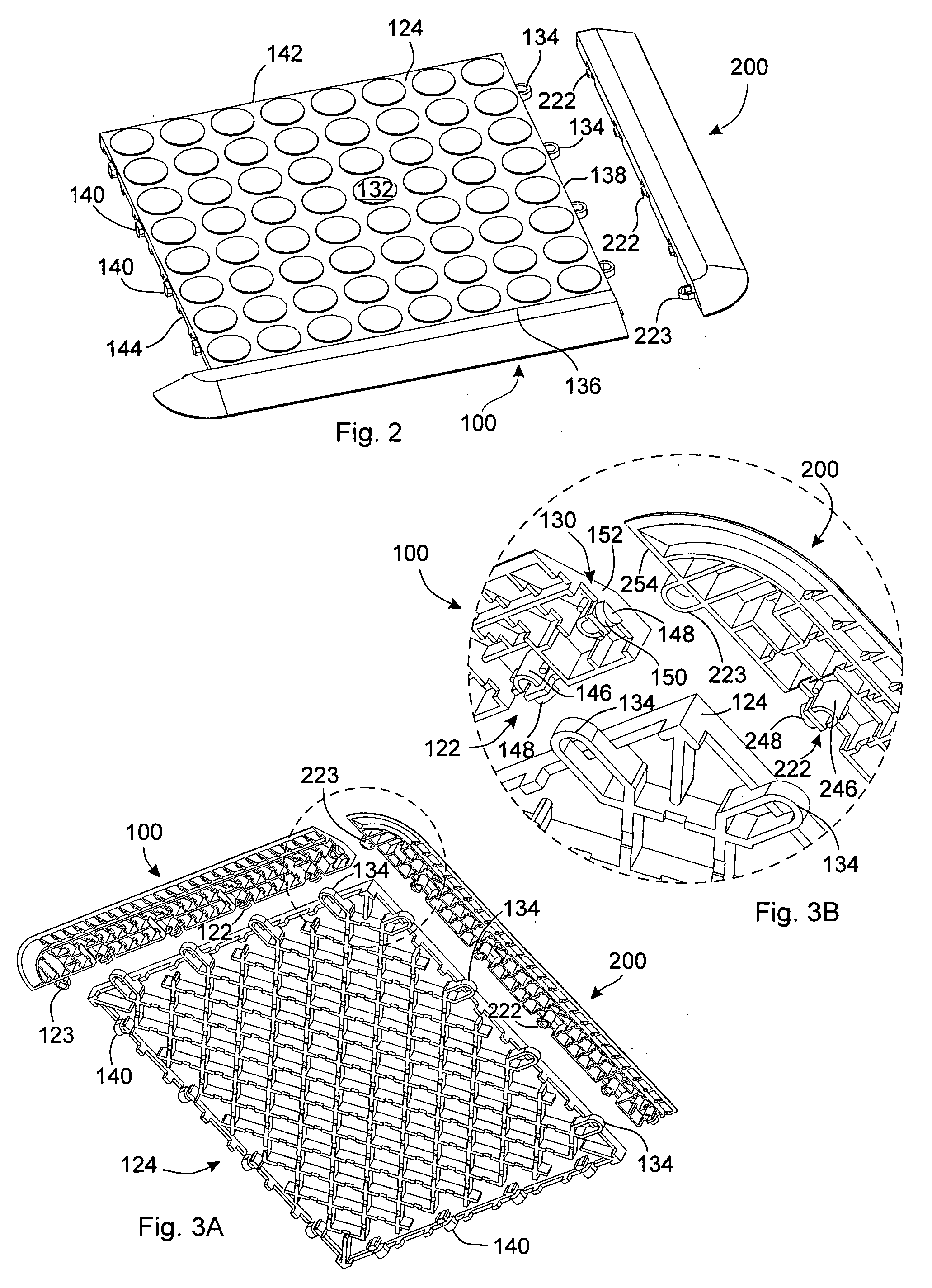
[0007] In one of many possible embodiments, the present invention provides a modular floor edge system. The modular floor edge system comprises a first ramp, the first ramp comprising a leading edge, a major axis and a minor axis, and a substantially vertical back substantially parallel to the major axis. The substantially vertical back comprises a plurality of connecting members removably attachable to a modular floor tile. The first ramp may include a tapered surface, an open webbed structure supporting the tapered surface, and the ramp may be made of plastic. According to some embodiments, the leading edge may comprise a substantially straight portion and a rounded corner. The ramp may include a substantially vertical side surface adjacent to and perpendicular with the substantially vertical back, the side surface comprising a connecting member attachable to another ramp. The plurality of connecting members may include male tabs comprising a generally vertical component and gener...


PUM

PropertyMeasurementUnit
angleaaaaaaaaaa
angleaaaaaaaaaa
angleaaaaaaaaaa

Abstract

The present invention provides a modular flooring system including a ramp to facilitate entry and exit from the flooring system. The ramp may be modular and interconnect with all or parts of a perimeter of the flooring system, and the ramp may also interconnect with adjacent ramp members.

Description

TECHNICAL FIELD [0001] This invention relates generally to floor tiles, and more particularly to modular floor systems with a transition edge. BACKGROUND OF THE INVENTION [0002] Floor tiles have traditionally been used for many different purposes, including both aesthetic and utilitarian purposes. For example, floor tiles of a particular color may be used to accentuate an object displayed on top of the tiles. Alternatively, floor tiles may be used to simply protect the surface beneath the tiles from various forms of damage. Floor tiles typically comprise individual panels that are placed on the ground either permanently or temporarily depending on the application. A permanent application may involve adhering the tiles to the floor in some way, whereas a temporary application would simply involve setting the tiles on the floor. Some floor tiles can be interconnected to one another to cover large floor areas such as a garage, an office, or a show floor. [0003] Various interconnection ...

Claims


Application Information

Patent Timeline
Patent Type & Authority Applications(United States)
IPC IPC(8): E04F15/00E04F11/16
CPCE04F15/10
Inventor MOLLER, JORGEN J. JR.
Owner SNAP LOCK INDS
Why Eureka
Try Eureka