Image forming system

a technology of image forming and printing system, which is applied in the direction of digital output to print units, visual presentation using printers, instruments, etc., can solve the problems of user being forced to perform a considerably troublesome operation and extremely troublesome input operation, and achieve the effect of convenient printing operation

Active Publication Date: 2006-01-26
BROTHER KOGYO KK
View PDF8 Cites 8 Cited by
  • Summary
  • Abstract
  • Description
  • Claims
  • Application Information

AI Technical Summary

Benefits of technology

[0011] The present invention provides an image forming system capable of more easily performing printing operation such that recording paper is switched to the next sheet of recording paper at every page break when a plurality of copies of printed matter, each copy including a predetermined number of pages, are produced by means of a page-layout printing function or a double-sided printing function.

Problems solved by technology

Therefore, there arises a problem of the user being forced to perform an extremely troublesome input operation.
. . , 294, 297, and 300.” Consequently, the user must perform considerably troublesome operation.
Such a problem is not limited solely to a case where page-layout printing is performed, but can also arise similarly in a case where double-sided printing is performed.

Method used


Image

  • Image forming system
  • Image forming system
  • Image forming system

Examples


first embodiment

[First Embodiment]

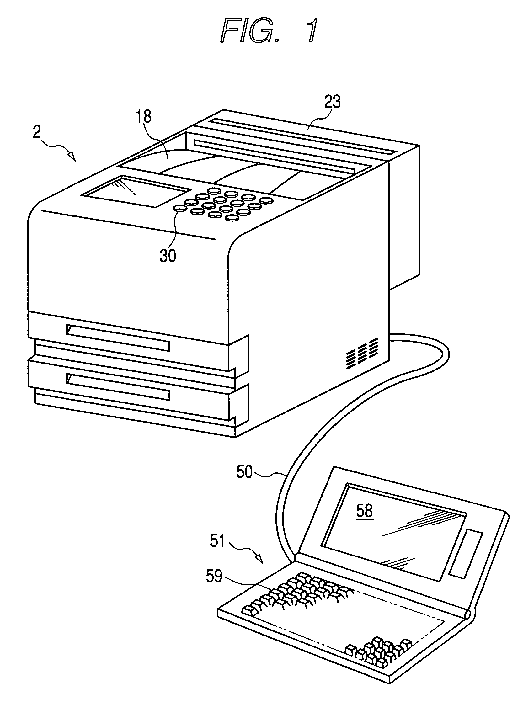
[0047] First, hardware constituting an image forming system will be described. FIG. 1 is a perspective view showing hardware constituting an image forming system.

[0048] The image forming system has a laser printer (hereinafter simply called a “printer”) 2 capable effecting double-sided printing, and a personal computer 51 connected to the printer 2 by way of a communications line 50.

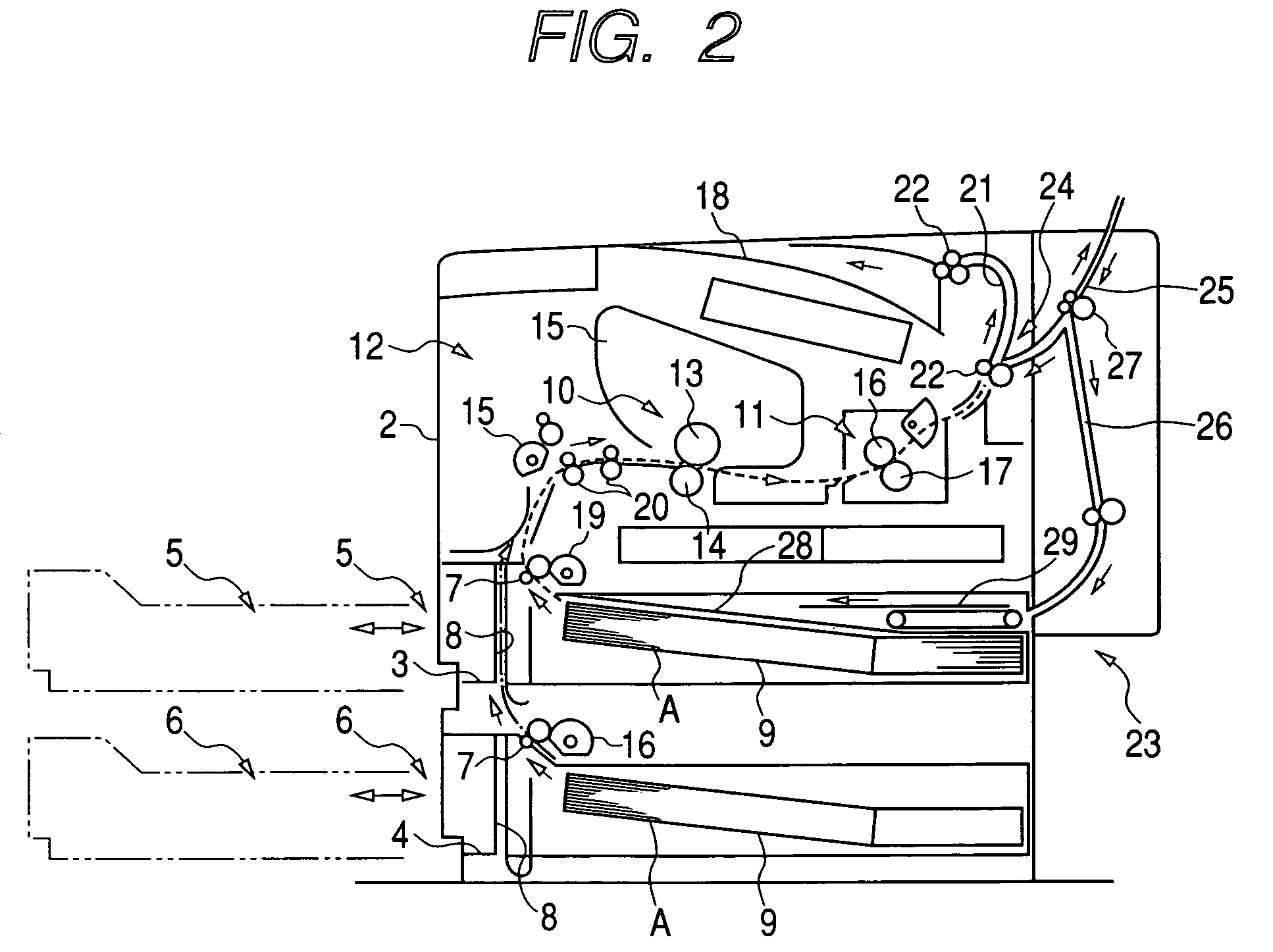
[0049] The structure of the printer 2 will now be described. FIG. 2 is a cross-sectional view of the printer 2.

[0050] A first cassette housing section 3 and a second cassette housing section 4, each of which has an open front, are formed one on top of the other within a lower internal portion of the printer 2. A first paper feeding cassette 5 is removably attached to the first cassette housing section 3, and a second paper feeding cassette 6 is removably attached to the second cassette housing section 4. The paper feeding cassettes 5, 6 are formed into the same shape, and a paper fee...

second embodiment

[Second Embodiment]

[0108] An embodiment differing from the first embodiment will now be described. A difference between the present embodiment and the first embodiment lies in processing executed by the previously-described personal computer 51 and that executed by the printer 2. Since no difference exists between the personal computer 51 and the printer 2 in view of hardware or the like, in the following description a detailed explanation is directed chiefly toward a difference between the first embodiment and the present embodiment, and explanations about the common configuration are omitted.

[0109] First, processing to be performed when an image forming system of the second embodiment performs page-layout printing will be described. In the image forming system of the first embodiment, the personal computer 51 receives printing conditions designated by the user; generates print data by means of which page-layout printing is performed in accordance with the printing conditions; and...

third embodiment

[Third Embodiment]

[0163] An embodiment differing from the first and second embodiments will now be described. A difference between the present embodiment and the first embodiment lies in processing to be executed by the personal computer 51. Since no difference exists between the personal computer 51 and the printer 2 in view of hardware or the like, in the following description a detailed explanation is directed chiefly toward a difference between the first embodiment and the present embodiment, and explanations about the common configuration are omitted.

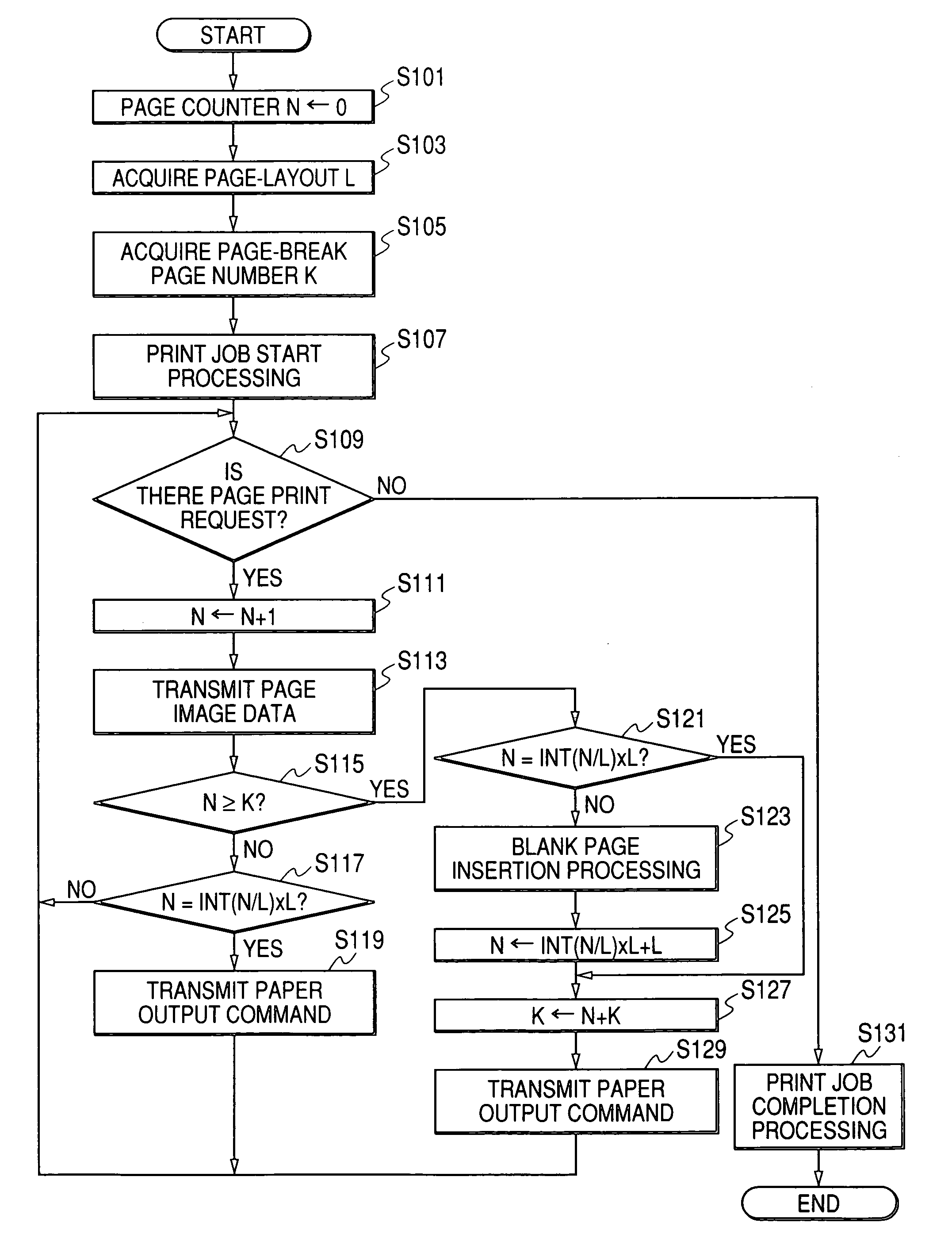
[0164] The first embodiment has provided illustration of independent flowcharts for page-layout print processing and double-sided printing. The print processing to be described below is complex print processing into which page-layout printing and double-sided printing are incorporated. Print processing to be described in the third embodiment is processing to be performed by the personal computer 51. In this respect, the present em...


PUM


Abstract

A personal computer acquires the number of pages L to be laid in one surface of a medium specified by a user, thereby acquiring a page number K to be considered to be a page break for one copy. A counter is incremented every time print data corresponding to one page are transmitted to a printer. When the value of the counter has exceeded the page-break page number K, recording of a top page of the next copy on the same recording paper is prevented by inserting a blank page, so long as the counter does not assume a multiple of the page number L.

Description

BACKGROUND OF THE INVENTION [0001] 1. Field of the Invention [0002] The present invention relates to an image forming system. [0003] 2. Description of the Related Art [0004] Conventionally, a printer, a copier, or a like machine performs page-layout printing operation, wherein images of L pages (where L is an integer satisfying a relationship of L≧2) are scaled down to be laid out within one page of recording paper. [0005] During such a page-layout printing operation, recording paper is switched to the next sheet of recording paper every time images of L pages are recorded on the recording paper. However, depending on contents for printing, there may arise a case where recording paper is desired to be switched at a page which does not correspond to a page break that arises every L pages. [0006] In response to such a demand, for example, JP-A-2002-316453 discloses a technique which enables “designation of a page-break position” when page-layout printing is performed. According to thi...

Claims


Application Information

Patent Timeline
Patent Type & Authority Applications(United States)
IPC IPC(8): G06K15/00
CPCG06K15/02
Inventor MORI, HIROMI
Owner BROTHER KOGYO KK
Why Eureka
Try Eureka