Image forming system
a technology of image forming and printing system, which is applied in the direction of digital output to print units, visual presentation using printers, instruments, etc., can solve the problems of user being forced to perform a considerably troublesome operation and extremely troublesome input operation, and achieve the effect of convenient printing operation
- Summary
- Abstract
- Description
- Claims
- Application Information
AI Technical Summary
Benefits of technology
Problems solved by technology
Method used
Image
Examples
first embodiment
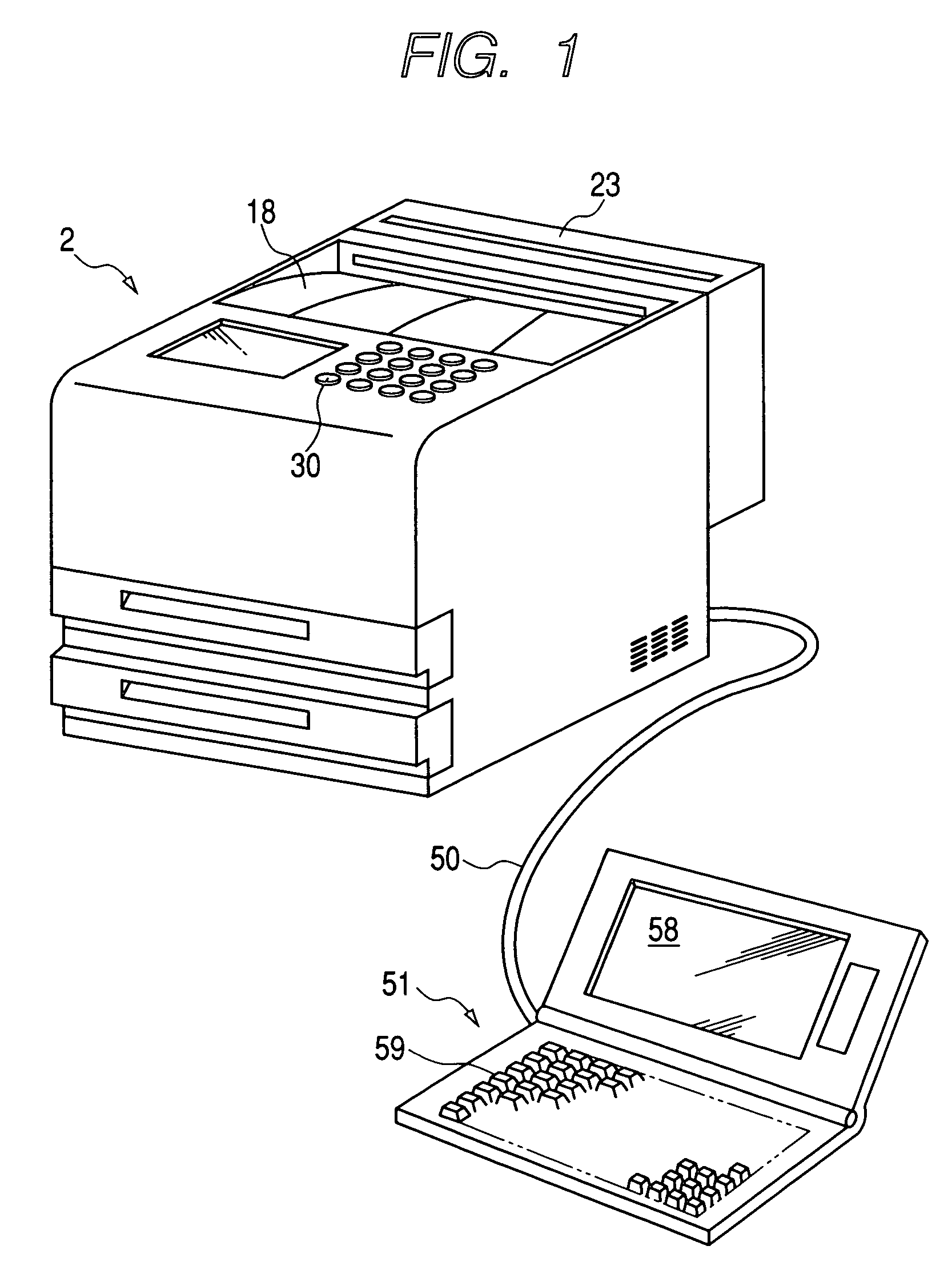
[0048]First, hardware constituting an image forming system will be described. FIG. 1 is a perspective view showing hardware constituting an image forming system.
[0049]The image forming system has a laser printer (hereinafter simply called a “printer”) 2 capable effecting double-sided printing, and a personal computer 51 connected to the printer 2 by way of a communications line 50.
[0050]The structure of the printer 2 will now be described. FIG. 2 is a cross-sectional view of the printer 2.
[0051]A first cassette housing section 3 and a second cassette housing section 4, each of which has an open front, are formed one on top of the other within a lower internal portion of the printer 2. A first paper feeding cassette 5 is removably attached to the first cassette housing section 3, and a second paper feeding cassette 6 is removably attached to the second cassette housing section 4. The paper feeding cassettes 5, 6 are formed into the same shape, and a paper feed roller 7 and a vertical...
second embodiment
[0109]An embodiment differing from the first embodiment will now be described. A difference between the present embodiment and the first embodiment lies in processing executed by the previously-described personal computer 51 and that executed by the printer 2. Since no difference exists between the personal computer 51 and the printer 2 in view of hardware or the like, in the following description a detailed explanation is directed chiefly toward a difference between the first embodiment and the present embodiment, and explanations about the common configuration are omitted.
[0110]First, processing to be performed when an image forming system of the second embodiment performs page-layout printing will be described. In the image forming system of the first embodiment, the personal computer 51 receives printing conditions designated by the user; generates print data by means of which page-layout printing is performed in accordance with the printing conditions; and transmits the thus-ge...
third embodiment
[0164]An embodiment differing from the first and second embodiments will now be described. A difference between the present embodiment and the first embodiment lies in processing to be executed by the personal computer 51. Since no difference exists between the personal computer 51 and the printer 2 in view of hardware or the like, in the following description a detailed explanation is directed chiefly toward a difference between the first embodiment and the present embodiment, and explanations about the common configuration are omitted.
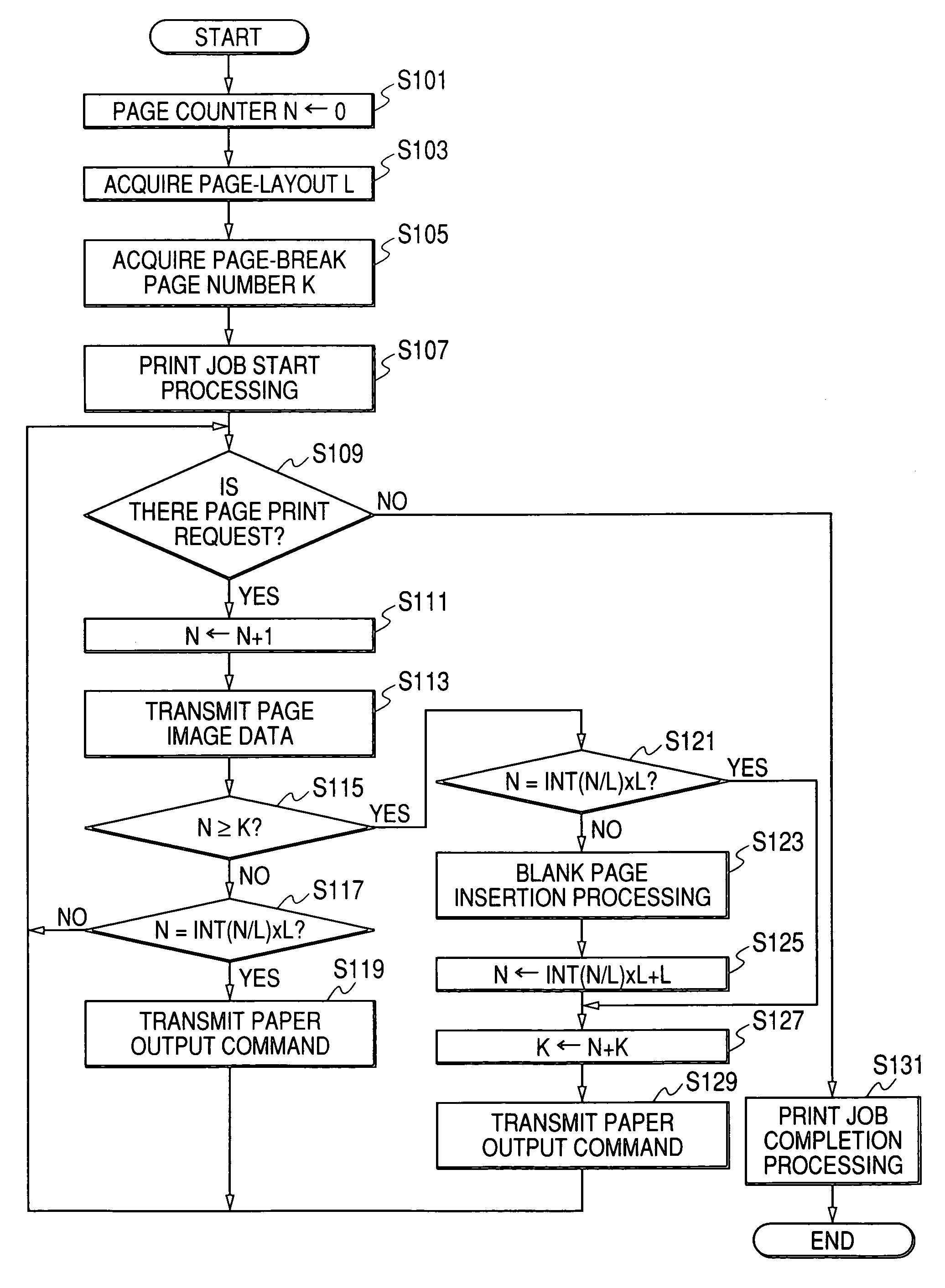
[0165]The first embodiment has provided illustration of independent flowcharts for page-layout print processing and double-sided printing. The print processing to be described below is complex print processing into which page-layout printing and double-sided printing are incorporated. Print processing to be described in the third embodiment is processing to be performed by the personal computer 51. In this respect, the present embodiment is closer to...
PUM
 Abstract
Description
Claims
Application Information
 - R&D
- Intellectual Property
- Life Sciences
- Materials
- Tech Scout
- Unparalleled Data Quality
- Higher Quality Content
- 60% Fewer Hallucinations
Browse by: Latest US Patents, China's latest patents, Technical Efficacy Thesaurus, Application Domain, Technology Topic, Popular Technical Reports.
© 2025 PatSnap. All rights reserved.Legal|Privacy policy|Modern Slavery Act Transparency Statement|Sitemap|About US| Contact US: help@patsnap.com


