Image forming apparatus

a technology of forming apparatus and forming tube, which is applied in the direction of electrographic process apparatus, thin material processing, instruments, etc., can solve the problem of increasing the cost of parts

a technology of forming apparatus and forming tube, which is applied in the direction of electrographic process apparatus, thin material processing, instruments, etc., can solve the problem of increasing the cost of parts

US20060018693A1Active Publication Date: 2006-01-26BROTHER KOGYO KK

Image

  • Image forming apparatus
  • Image forming apparatus
  • Image forming apparatus

Examples


Embodiment Construction

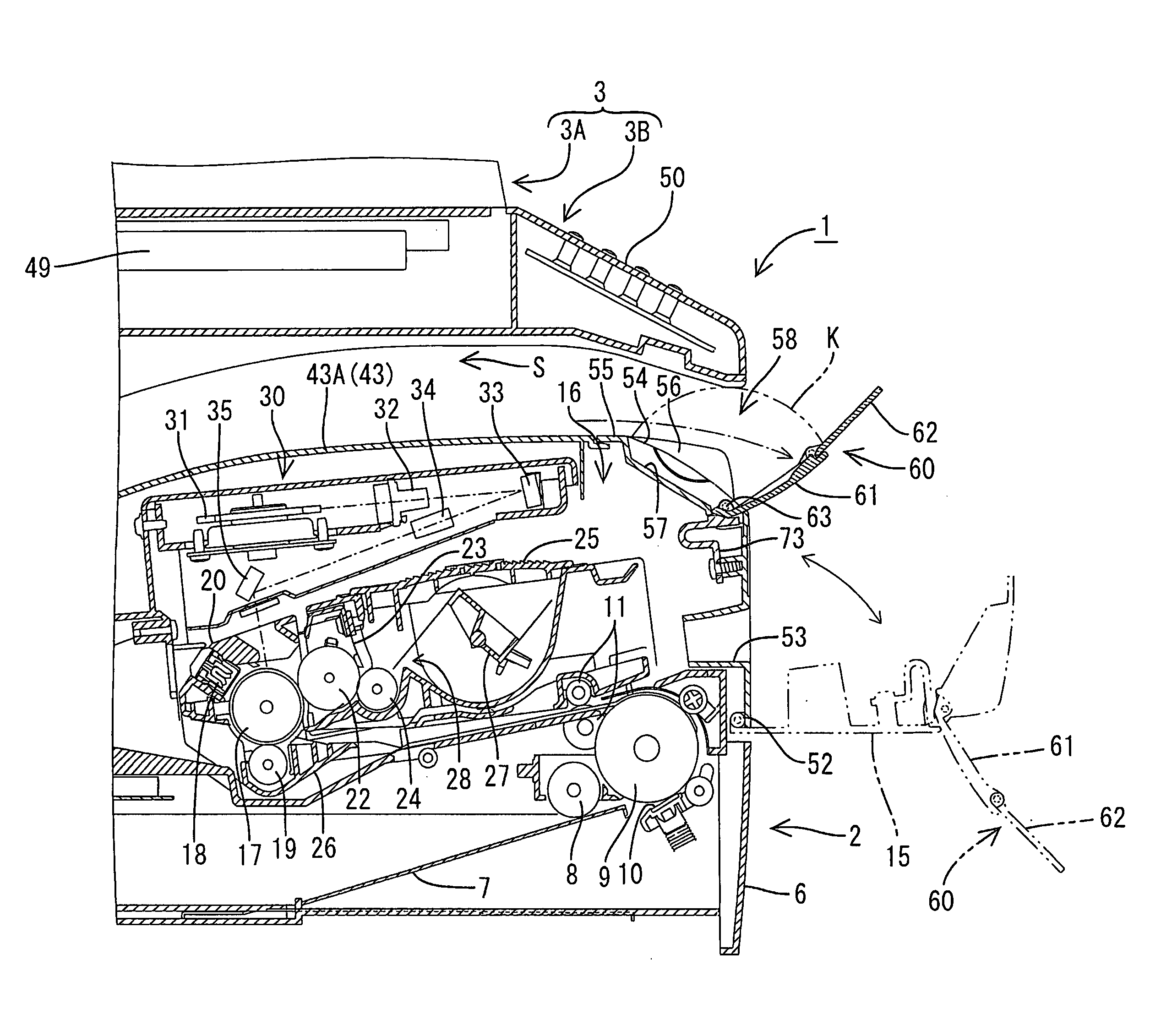
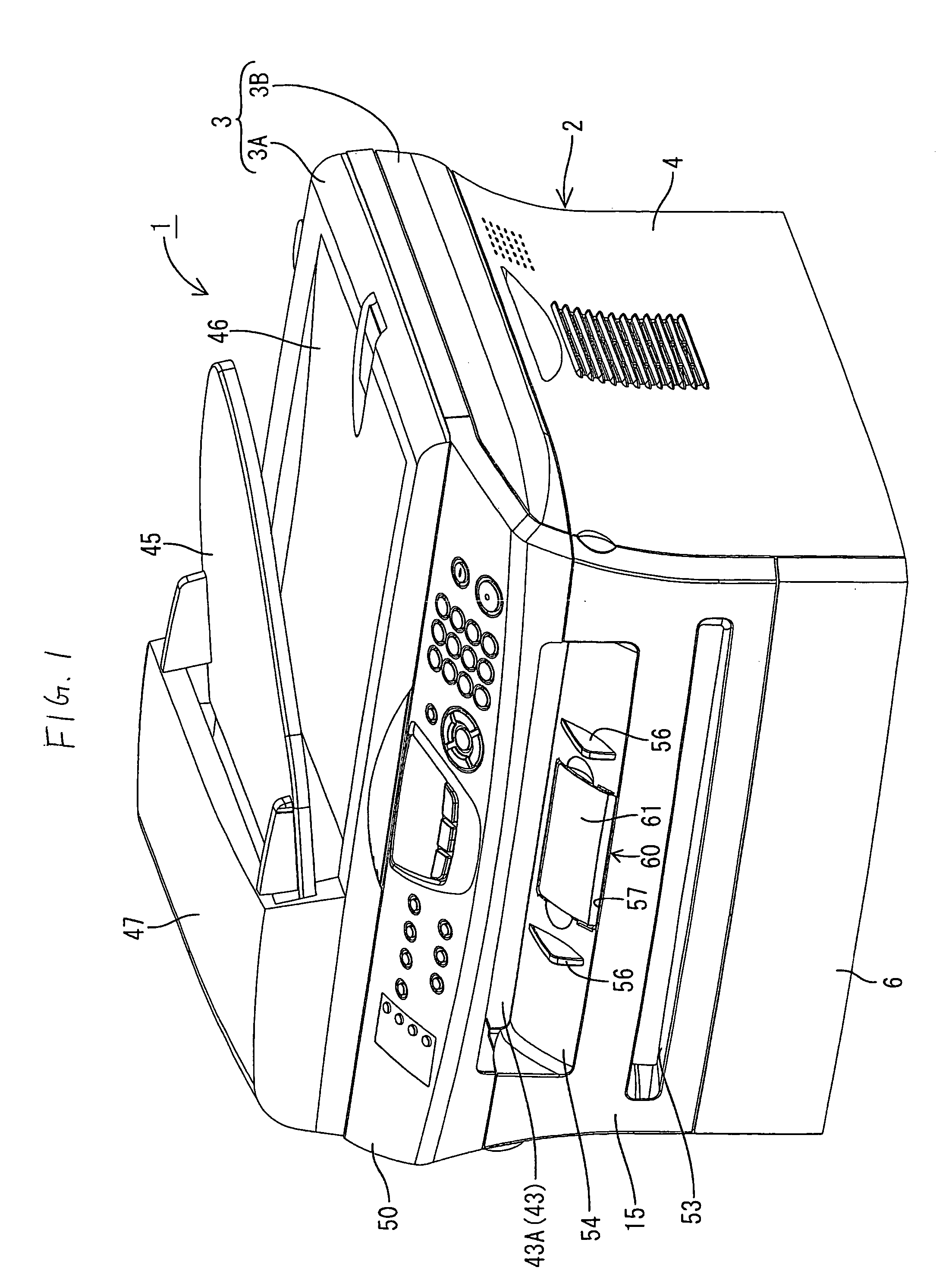
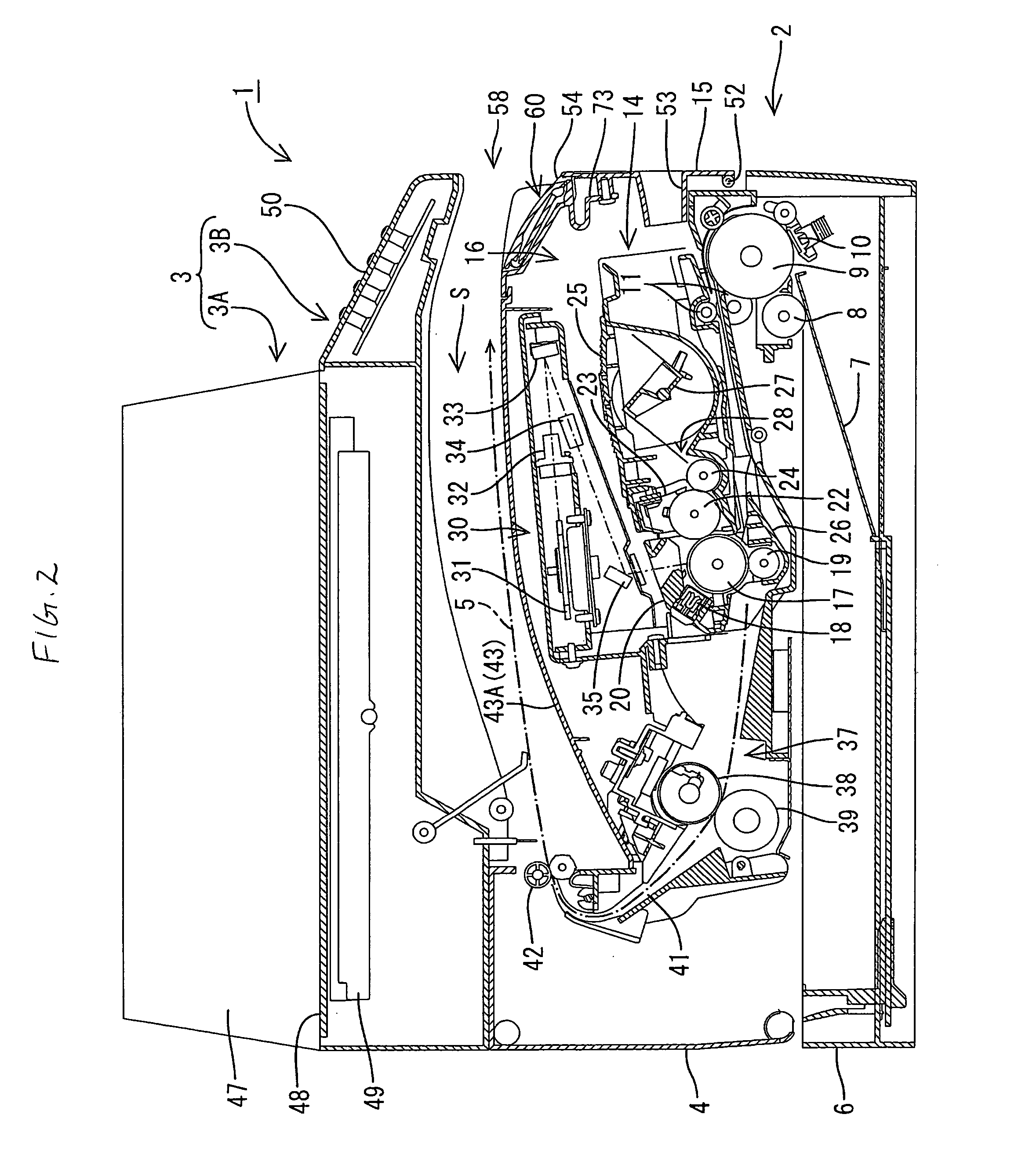
[0034] An embodiment of the invention will be described below with reference to FIGS. 1 to 9. The overall configuration of an image forming apparatus 1 will be described first with reference to FIGS. 1 and 2. FIG. 1 is a perspective view showing the external appearance of the image forming apparatus 1. FIG. 2 is a sectional view showing important part of the image forming apparatus 1. Incidentally, in the following description, up-down directions are defined on FIG. 2 and front-rear directions are defined so that the right in FIG. 2 is regarded as “front”.

[0035] The image forming apparatus 1 according to this embodiment is a combination machine including a printer function, a copying function, a scanner function, etc. The image forming apparatus 1 comprises an apparatus body 2, and a cover body 3 put on an upper surface of the apparatus body 2.

[0036] The apparatus body 2 includes a body casing 4 substantially shaped like a box as a whole. A paper feed tray 6 is provided in a lower...


PUM

PropertyMeasurementUnit
sizeaaaaaaaaaa
lengthaaaaaaaaaa
distanceaaaaaaaaaa

Abstract

An image-forming apparatus includes a body casing having on upper surface thereof a paper ejection tray on which a sheet of paper ejected after formation of an image is stacked; a side cover capable of opening and closing a side surface of the body casing on the downstream side in the direction of ejection of the sheet of paper so as to cover the side surface of the body casing; and an extension tray being attached to an upper portion of the side cover. The extension tray is capable of extending to the downstream side in the direction of ejection of the sheet of paper with respect to the paper ejection tray so as to support an end portion of the sheet of paper.

Description

BACKGROUND OF THE INVENTION [0001] 1. Field of the Invention [0002] The present invention relates to an image forming apparatus such as a printer, a copying machine, a facsimile machine, etc. [0003] 2. Description of the Related Art [0004] As an image forming apparatus such as a printer, there has been heretofore known an image forming apparatus having a paper ejection tray which is formed on an upper surface of a body casing so that a sheet of paper ejected after formation of an image can be stacked on the paper ejection tray. For example, in this type image forming apparatus described in JP-A-2002-104694, an extension tray for receiving a large-size sheet of paper is attached to the upper surface of the body casing. In use, the extension tray is fixed with a posture extending to the downstream side in the direction of ejection of the sheet of paper with respect to the paper ejection tray so that the movement of the sheet of paper in the direction of ejection of the sheet of paper ...

Claims


Application Information

Patent Timeline
26 Jan 2006
Publication
US20060018693A1
IPC
G03G15/00
CPC
B65H31/20; G03G15/6552; B65H2301/51256
Inventors
NOBE, HIROSHI; ITO, SAKAE