Banner station for glassy surface

a technology of glassy surface and banner, which is applied in the direction of machine supports, instruments, signs, etc., can solve the problems of unreliable fixing of the top and bottom of the banner to the transverse rod, increased safety concerns, and easy detachment of the banner from the support, so as to facilitate the movement, handling and management, and maximize the utilization of space. , the effect of convenient attachment/detachmen

Inactive Publication Date: 2010-01-19
WOO
View PDF9 Cites 0 Cited by
  • Summary
  • Abstract
  • Description
  • Claims
  • Application Information

AI Technical Summary

Benefits of technology

[0027]The banner stand according to the present invention makes it possible to vary the display direction of a banner, which is mounted on the banner stand, in any direction so that the banner faces the advertisement target, i.e. eyes of passers-by, as desired.
[0028]The inventive banner stand needs no weight, i.e. support member for supporting a banner on the ground and releases the vacuum condition of the vacuum suction support frequently, so that the banner can be easily attached / detached. This enables convenient movement, handling, and management.
[0029]In addition, the banner is directly installed on a wall surface of a building (e.g. room, office) so as to maximize space utilization without interfering with pedestrians in corridors or outside the building.

Problems solved by technology

However, this type of banner has a problem in that fixation of the top and bottom of the banner to the transverse rods is unreliable, because the fixation simply depends on engagement between the support frames, which are placed on the top and bottom of the banner, and the transverse rods.
As a result, the banner easily detaches from the support due to strong wind, for example, and flaps in the wind.
This increases safety concerns, adversely affects the merits of advertisements or announcements, and degrades the aesthetic view of streets.
Furthermore, the fact that a separate support must be fixed to the ground restricts the selection of installation place and costs a large amount of money.
However, the fixed stand has a problem in that its installation involves complicated and inconvenient procedures.
Therefore, although the fixed stand may pose no problem when it remains fixed for a long period of time, it is not suited to frequent installation and removal.
In addition, the mounting holes remain on the wall surface even after removal of the stand and adversely affect the interior of the building.
However, the rotatable suction device has a problem in that, when the operation unit is rotated, external force acts on the suction plate and tends to rotate it together with the operation unit.
This causes the suction plate to slip on the wall surface.
Such a slip adversely affects the suction force between the wall surface and the suction plate.
However, the fact that the bolt at the center of the suction plate is used to fix the end, which protrudes upwards from the through-hole of the operation unit, with the nut makes it difficult to maintain the bottom surface of the suction plate in an initially flat condition before the suction plate is operated.
This means that, when the bottom surface of the suction plate is not flat after the nut is coupled to the bolt, the suction force exerted by the suction plate decreases seriously.
This weakens the suction force of the rotatable suction device little by little.
The removable flagpole fixing apparatus has a problem in that, whenever the rotatable flagpole is separated from the flagpole support, the clip portion must be separated from the flagpole support in advance.
Such a requirement on the size of the flagpole support and the clip portion inevitably weakens the gripping force of the rotatable flagpole, which is supported between the flagpole support and the clip portion.
This has a problem in that, when the rotatable flagpole is slanted at an angle, it is difficult to maintain the slanted condition for a long period of time.

Method used


Image

  • Banner station for glassy surface
  • Banner station for glassy surface
  • Banner station for glassy surface

Examples


Embodiment Construction

[0036]Reference will now be made in detail to the preferred embodiments of the present invention.

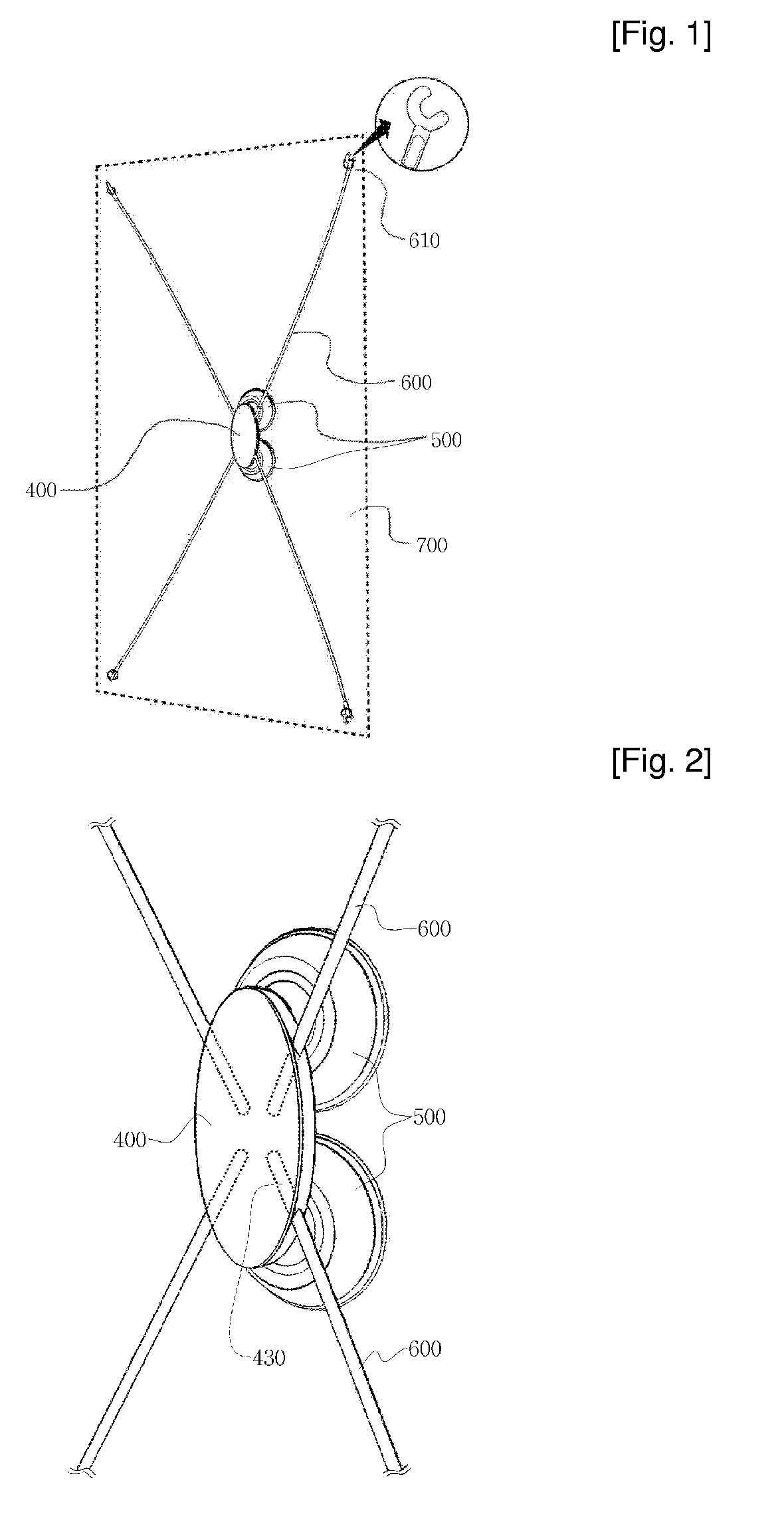
[0037]The present invention is directed to a banner stand which can easily attach to and detach from a smooth and hard surface, such as glass or tiles, and which can conveniently modify the display direction after attachment.

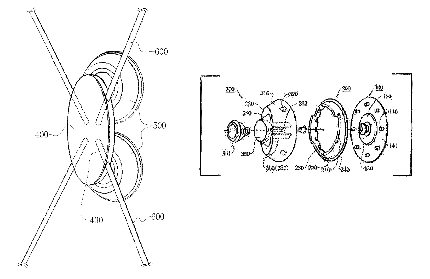
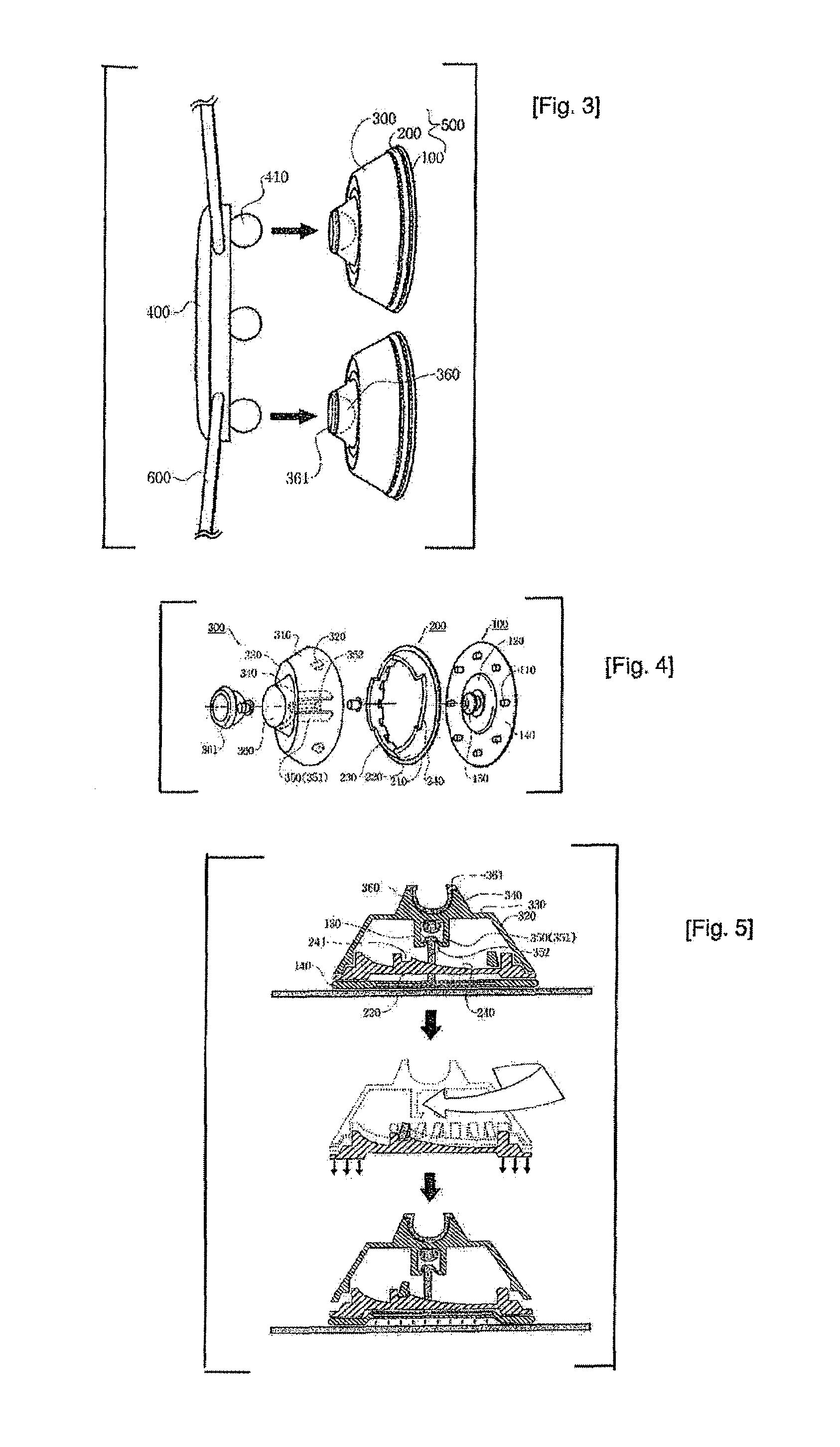
[0038]A banner stand according to an embodiment of the present invention is adapted to attach to and detach from a glassy surface. The banner stand includes a disk-shaped vacuum suction plate having a flat bottom surface, a number of fixing protrusions integrally formed along a peripheral edge of an upper surface, a circular latching protrusion base protruding from a central portion inside the fixing protrusions so as to form a step, and a suction latching protrusion protruding from a central portion of the latching protrusion base; a lower support having an annular base ring portion fastened to a peripheral edge of an upper surface of the vacuum suction plate, a sla...


PUM


Abstract

Disclosed is a banner stand adapted to attach to and detach from a glassy surface. The banner stand includes a vacuum suction plate made of a soft material, a suction latching protrusion protruding from the vacuum suction plate; a lower support having a slanted lateral wall portion formed along a peripheral edge of an upper end of a base ring portion, the slanted lateral wall portion having operation ribs extending thereon at an interval; a suction plate operation member having rib guide protrusions guided on the operation ribs, a suction latching protrusion support, and a ball joint coupler; and a pole support having a pair of ball joints positioned on a bottom surface of a body so as to be coupled to the ball joint coupler of the suction plate operation member.

Description

TECHNICAL FIELD[0001]The present invention relates to a banner stand adapted to easily attach to and detach from a smooth and hard surface, such as glass or tiles.BACKGROUND ART[0002]In general, various shapes of banners are placed along streets in the transverse or longitudinal direction with commercial advertisements or event announcements printed thereon.[0003]In the case of a banner placed in the longitudinal direction, it is customary to position a support in the vertical direction and install a pair of transverse rods along the longitudinal direction of the support in such a manner that the rods are spaced a distance corresponding to the longitudinal length of the banner. The top and bottom of the banner engage with the transverse rods so as to be fixed thereto, respectively. To this end, the banner has support frames placed at its top and bottom, respectively. The support frames extend as much as the transverse length of the banner.[0004]However, this type of banner has a pro...

Claims


Application Information

Patent Timeline
Patent Type & Authority Patents(United States)
IPC IPC(8): F16B47/00
CPCG09F15/0025G09F17/00G09F7/02G09F15/00G09F19/16
Inventor WOO, CHEOL-SEOK
Owner WOO
Why Eureka
Try Eureka