Printing plate unit, printing plate attachment device and printer

a printing plate and attachment device technology, applied in printing presses, printing presses, rotary presses, etc., can solve the problems of difficult detachment/attachment of the plate cylinder from/to the plate driving shaft, inaccurate attachment of the printing plate to the plate cylinder, etc., to achieve the effect of large space for storing the printing plate and easy attachment/detachment to/from the printer

Active Publication Date: 2016-08-23
IZUME MASAYUKI
View PDF8 Cites 1 Cited by
  • Summary
  • Abstract
  • Description
  • Claims
  • Application Information

AI Technical Summary

Benefits of technology

[0059]As described above, the printing plate unit according to the present invention can be readily attached / detached to / from the printer. Moreover, the printing plate detached from the printing plate coupling member can be stored in the form of a flat plate and therefore, a large space for storing the printing plate is not required.
[0060]In the printing plate attachment device and the printer according to the present invention, as described above, attachment, detachment, and fixing of the printing plate with respect to the printer can be achieved readily and accurately.

Problems solved by technology

In this case, the operation of attaching the printing plate in the printer is cumbersome, making accurate attachment of the printing plate to the plate cylinder difficult.
In this case, since the plate cylinder is substantially heavy, it is difficult to detach / attach the plate cylinder from / to the plate driving shaft.

Method used


Image

  • Printing plate unit, printing plate attachment device and printer
  • Printing plate unit, printing plate attachment device and printer
  • Printing plate unit, printing plate attachment device and printer

Examples


Embodiment Construction

[0073]Some embodiments of the present invention will be described below with reference to figures.

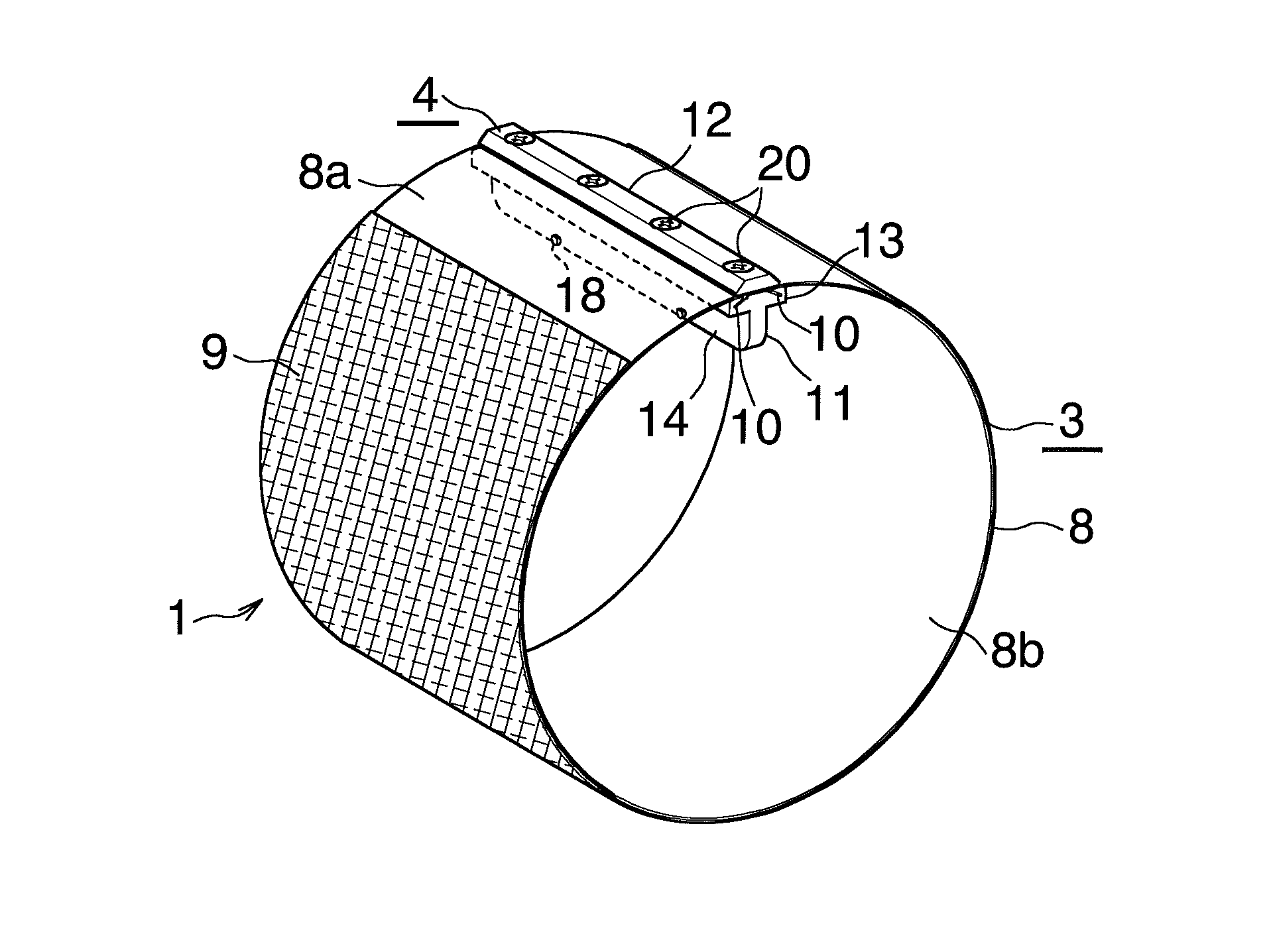
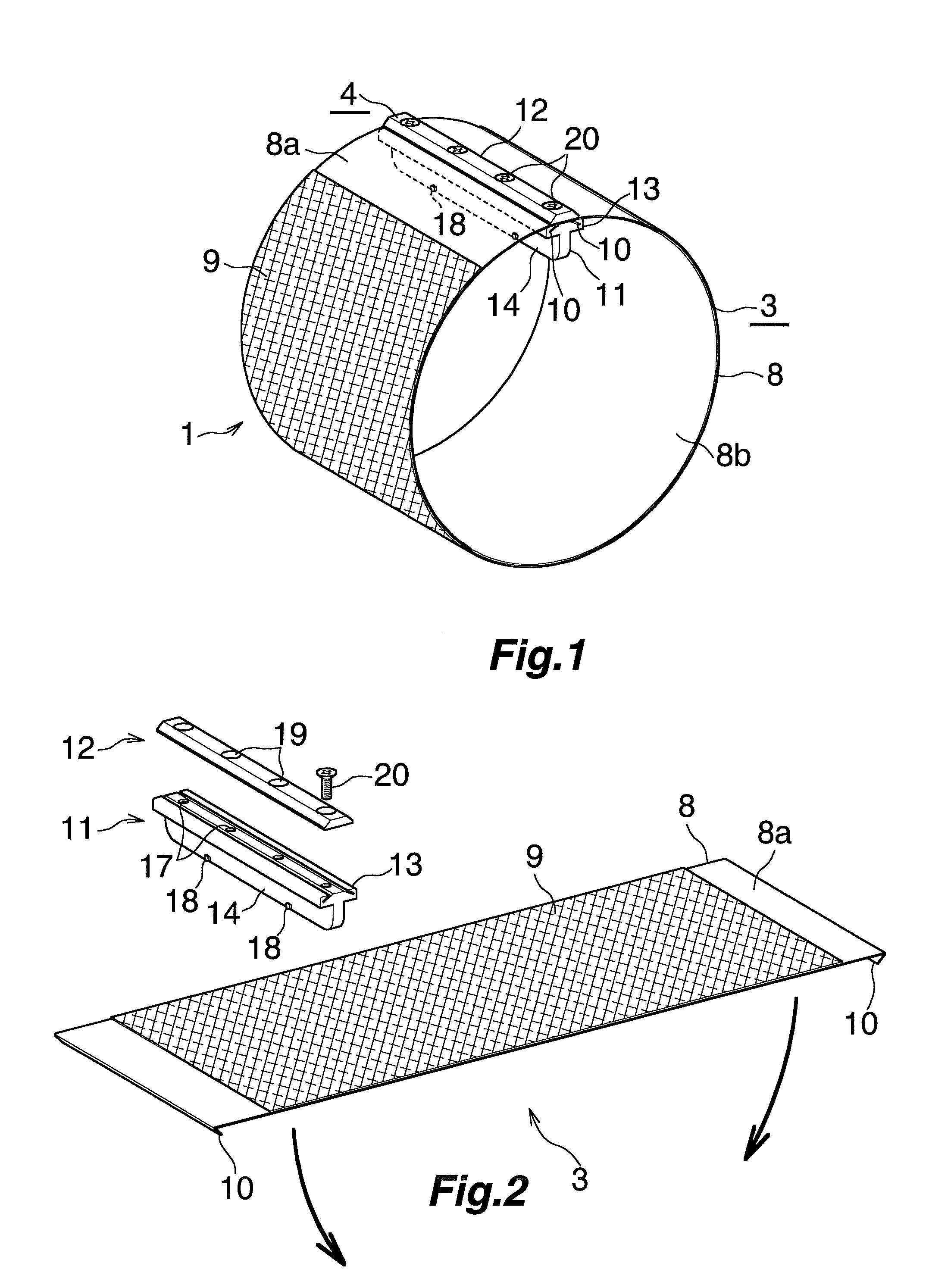
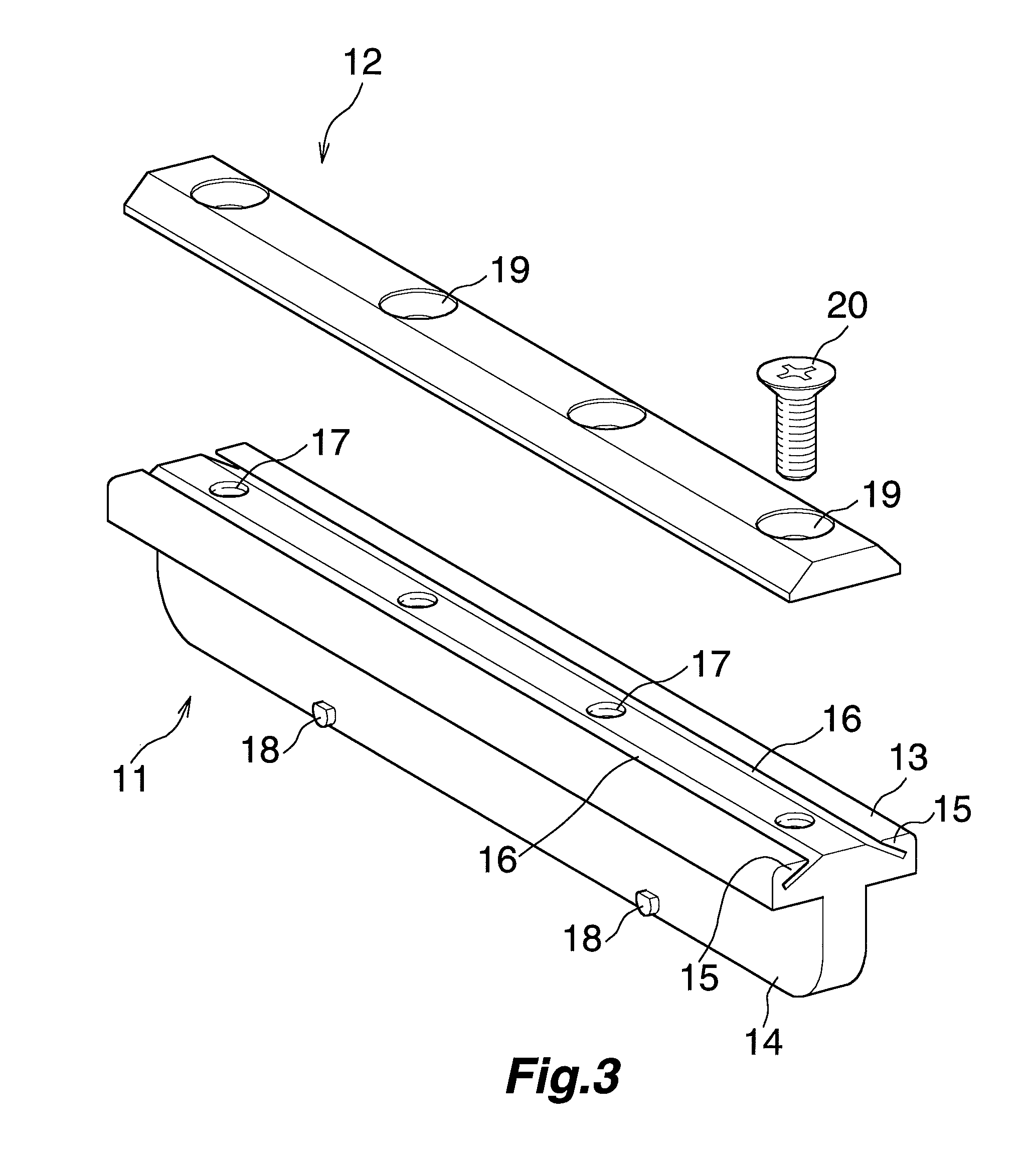
[0074]FIG. 1 to FIG. 3 show an embodiment of a printing plate unit (1), FIG. 4 to FIG. 9 show an embodiment of a printing plate attachment device (2), and FIG. 10 to FIG. 12 show another embodiment of the printing plate unit (1).

[0075]As shown in FIG. 1, the printing plate unit (1) is formed by coupling ends of a sheet-like printing plate (3) to each other with a printing plate coupling member (4) to be cylindrical. The coupling member (4) constitutes a part of the printing plate attachment device (2).

[0076]As shown in FIG. 4, the printer includes a horizontally-arranged plate driving shaft (5). One end of the shaft (5) is rotatably supported by a bearing housing (6) provided in a frame of a printer not shown, and the other end of the shaft (5) is rotatably supported by a bearing housing not shown provided in the frame. The printing plate attachment device (2) is detachably fixed such t...


PUM


Abstract

To attach a printing plate to a printer readily and accurately, and avoid necessity of a large space for the storage of the printing plate. A printing plate unit 1 includes a printing plate 3 in which a plate section 9 is provided on a part of a front surface of a sheet 8 made of an elastic material and engaging protrusions 10 that protrude toward a back surface and extend in a width direction are provided at both longitudinal ends, and a printing plate coupling member 4 that is detachable from the printing plate 3 and couples both the engaging protrusions 10 of the cylindrical printing plate 3 to each other to keep the cylindrical shape of the printing plate 3.

Description

TECHNICAL FIELD[0001]The present invention relates to a printing plate unit, a printing plate attachment device, and a printer.BACKGROUND ART[0002]A printer in which a printing plate is attached to the outer periphery of a plate cylinder fixed to a plate driving shaft has been known.[0003]In such printer, a sheet-like printing plate may be attached by being wound around the plate cylinder fixed to the plate driving shaft. In this case, the operation of attaching the printing plate in the printer is cumbersome, making accurate attachment of the printing plate to the plate cylinder difficult.[0004]To avoid this situation, after winding the sheet-like printing plate around the plate cylinder removed from the plate driving shaft, the plate cylinder may be fixed to the plate driving shaft. In this case, since the plate cylinder is substantially heavy, it is difficult to detach / attach the plate cylinder from / to the plate driving shaft.[0005]Inventor proposes a printing plate that can be a...

Claims


Application Information

Patent Timeline
Patent Type & Authority Patents(United States)
IPC IPC(8): B41F27/12B41F27/06B41F13/20
CPCB41F13/20B41F27/1237B41F27/06B41F27/12B41F27/1231B41P2227/41
Inventor IZUME, MASAYUKI
Owner IZUME MASAYUKI
Why Eureka
Try Eureka