Seat slide device

a technology of seat and slide, which is applied in the direction of machine supports, transportation and packaging, and other domestic objects, and can solve problems such as unpractical devices

Inactive Publication Date: 2006-02-02
AISIN SEIKI KK
View PDF0 Cites 8 Cited by
  • Summary
  • Abstract
  • Description
  • Claims
  • Application Information

AI Technical Summary

Problems solved by technology

This space may cause a rattling, especially vibrations of the upper rail against the lower rail in a vertical direction.
This makes the device unpractical.

Method used


Image

  • Seat slide device
  • Seat slide device
  • Seat slide device

Examples


Embodiment Construction

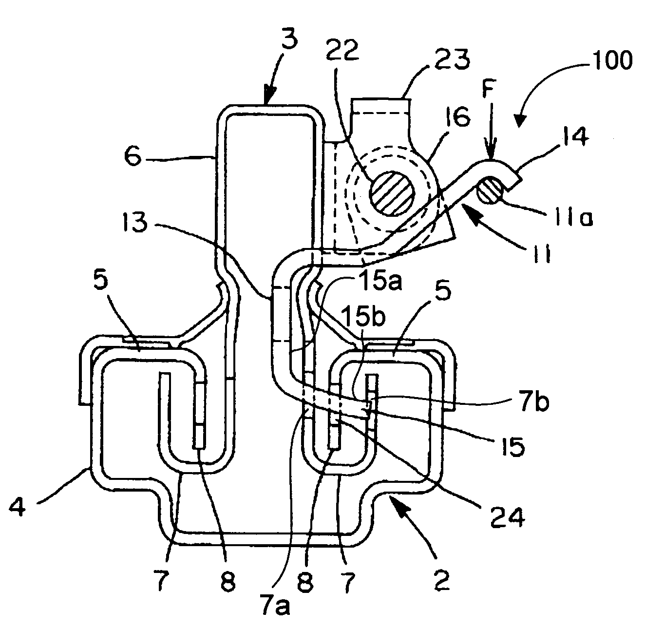
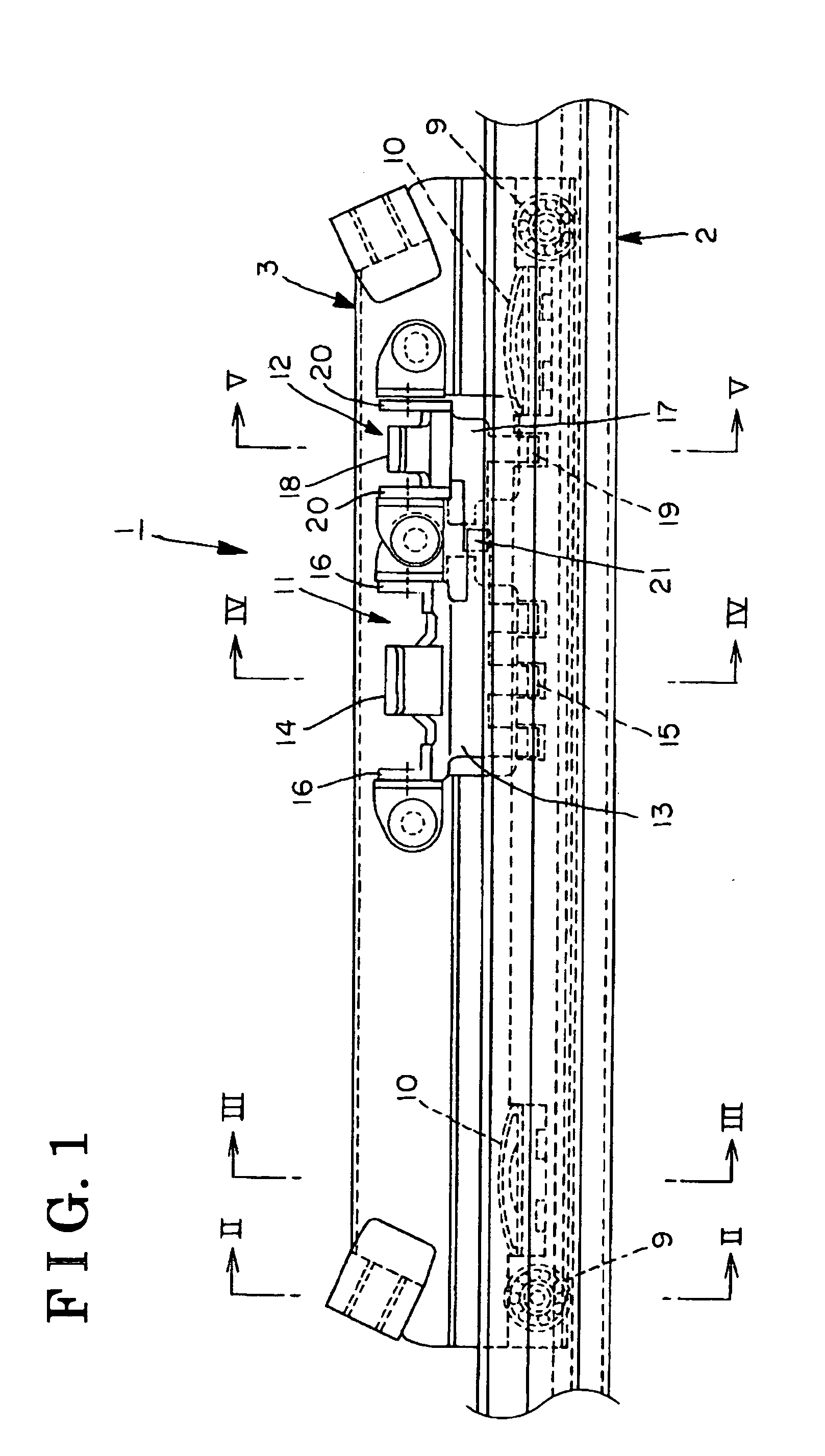
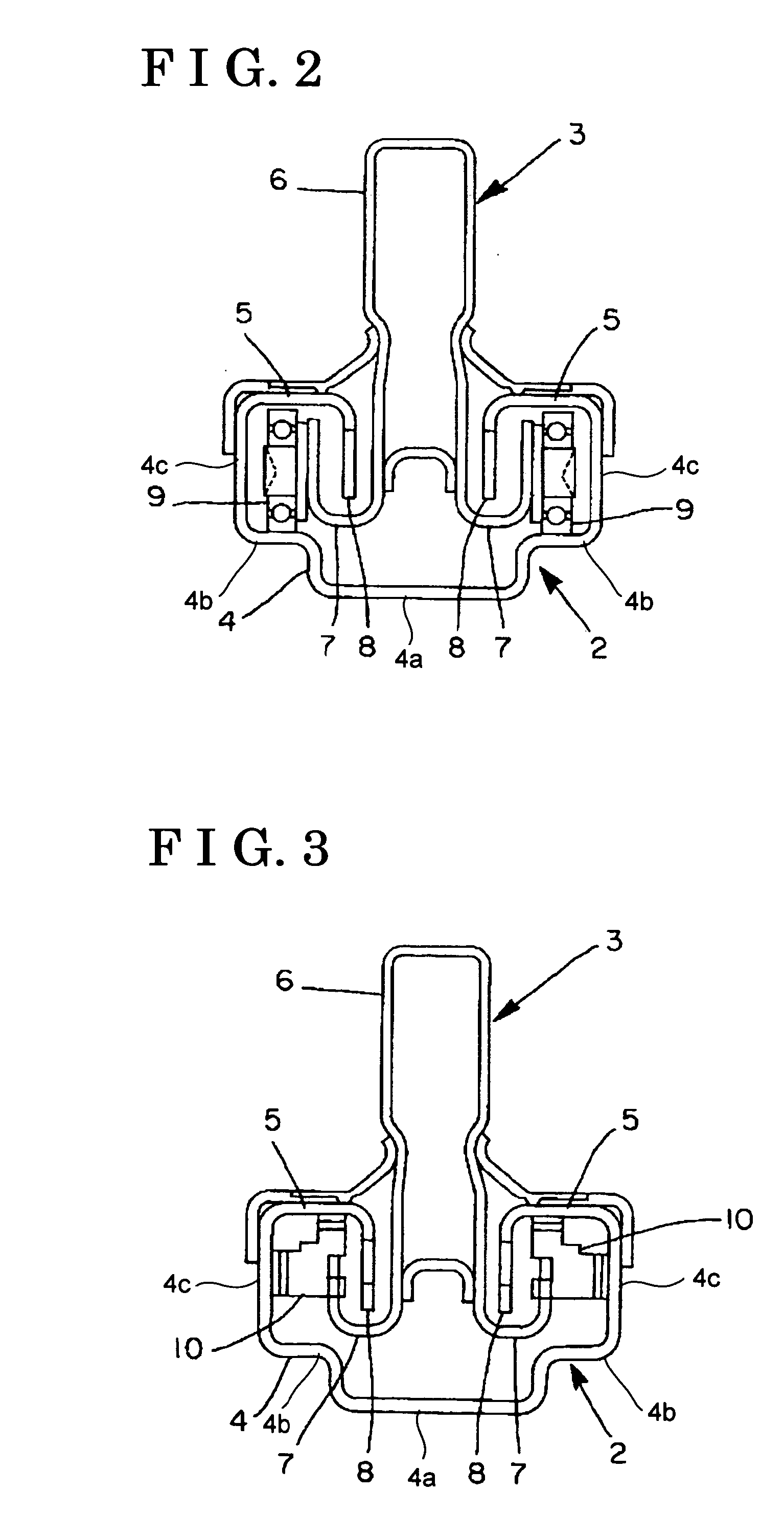
[0022] As shown in FIG. 1, a seat slide device 1 for a vehicle includes a lower rail 2, which is fixed on the vehicle floor, and an upper rail 3, which is provided so as to be slidable on the lower rail 2. Further, the seat slide device 1 includes a lock and unlock mechanism 100 for locking (engaging) and unlocking (disengaging) the upper rail 3 relative to the lower rail 2. As shown in FIG. 2, the lower rail 2 is comprised of a main body portion 4 and flange portions 5.

[0023] Specifically, the main body portion 4 includes vertical wall portions 4c and a first bottom portion 4a provided between the vertical wall portions 4c. Both end portions of the first bottom portion 4a are stepped so as to form second bottom portions 4b. Thus, the main body portion 4 is formed in approximately a U-shape in cross section.

[0024] Further, each of the flange portions 5 is formed so as to extend inward from an upper end of each of the vertical wall portions 4c. The flange portions 5 further extend ...


PUM


Abstract

A seat slide device comprises a lower rail fixed to a vehicle floor, an upper rail supporting a seat, a lock and unlock mechanism including a main lock plate and a sub lock plate for maintaining the upper rail so as to be slidable on the lower rail, the main lock plate rotatably supported by a first bracket fixed to the upper rail, the sub lock plate rotatably supported by a second bracket fixed to the upper rail, an engaging hole formed on the lower rail, and a claw portion formed on the sub lock plate so as to contact to an upper surface of the engaging hole in order to press down the upper rail.

Description

CROSS REFERENCE TO RELATED APPLICATIONS [0001] This application is based on and claims priority under 35 U.S.C. § 119 to Japanese Patent Application 2004-219055, filed on Jul. 27, 2004, the entire content of which is incorporated herein by reference. FIELD OF THE INVENTION [0002] This invention relates to a seat slide device by which a rattling of an upper rail against a lower rail can be reduced. BACKGROUND [0003] A known seat slide device includes a lower rail fixed on a vehicle floor and an upper rail positioned so as to be slidable on the lower rail. In this configuration, a seat is fixed on the upper rail. [0004] In order to smooth the movement of the upper rail sliding on the lower rail, a bearing is provided between the upper rail and the lower rail. Specifically, the bearing is supported by the upper rail so as to rotate on the lower rail. [0005] Further, the seat slide device includes a lock and unlock mechanism for locking (engaging) and unlocking (disengaging) the upper r...

Claims


Application Information

Patent Timeline
Patent Type & Authority Applications(United States)
IPC IPC(8): F16M13/00
CPCB60N2/0715B60N2/0893B60N2/0843B60N2/0825
Inventor YAMADA, TAKAHIROOKAZAKI, HIROYUKITANAKA, TOSHIYUKI
Owner AISIN SEIKI KK
Why Eureka
Try Eureka