

Fuel cell
- Summary
- Abstract
- Description
- Claims
- Application Information
AI Technical Summary
Benefits of technology
Problems solved by technology
Method used
Image

Examples
first embodiment
[0024] There will be firstly explained a fuel cell of a first embodiment according to the present invention in detail with reference to FIG. 1 through FIG. 11C.
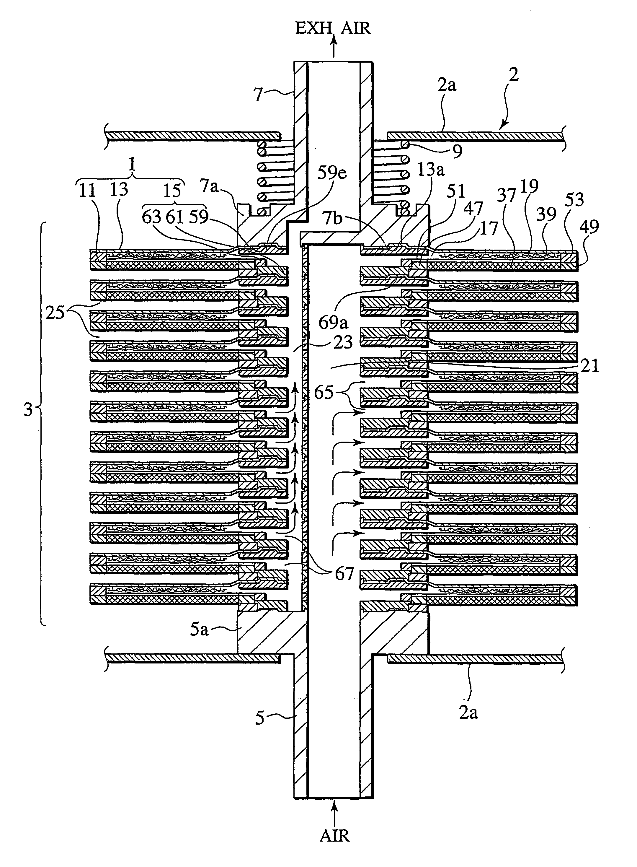
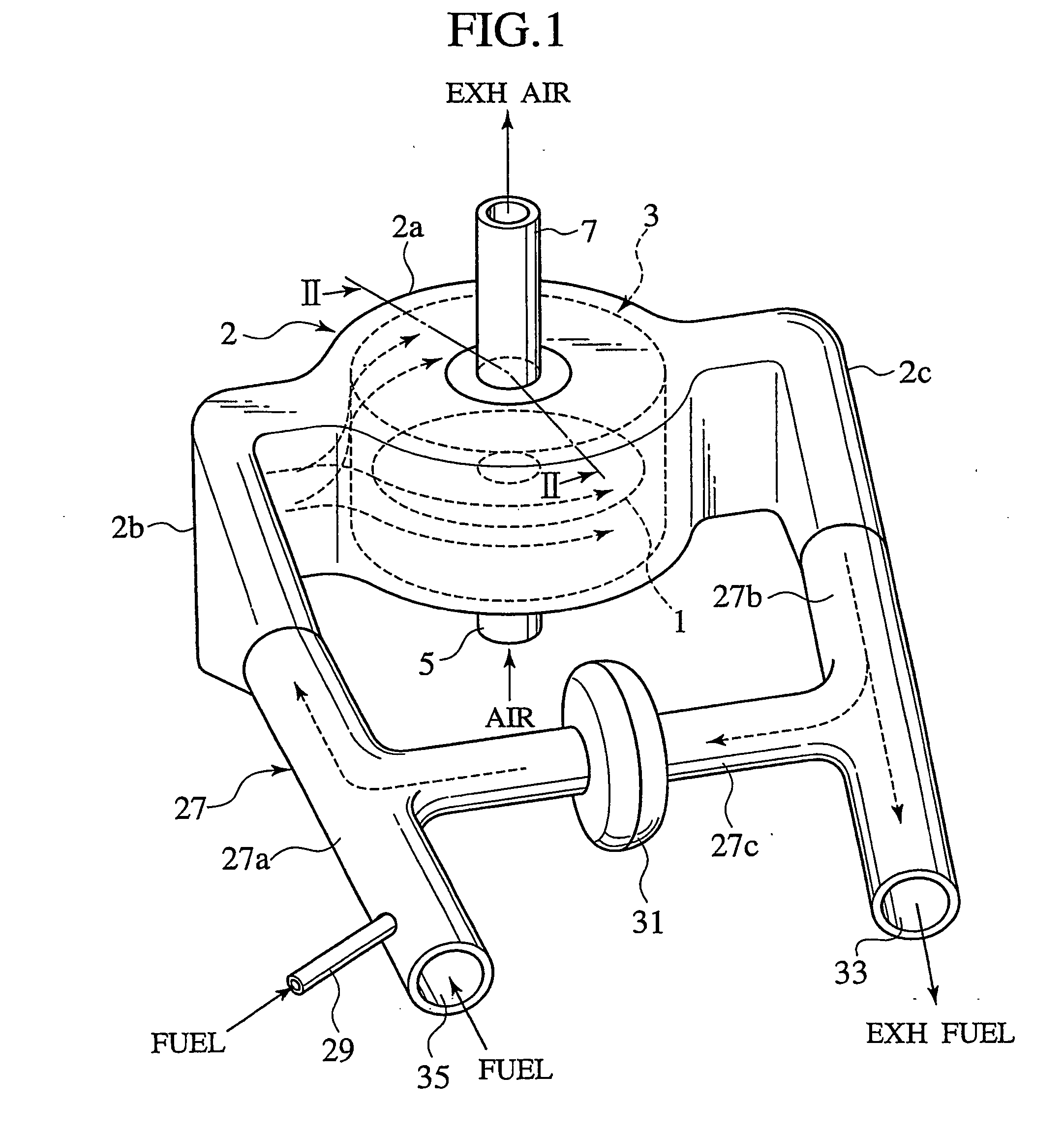
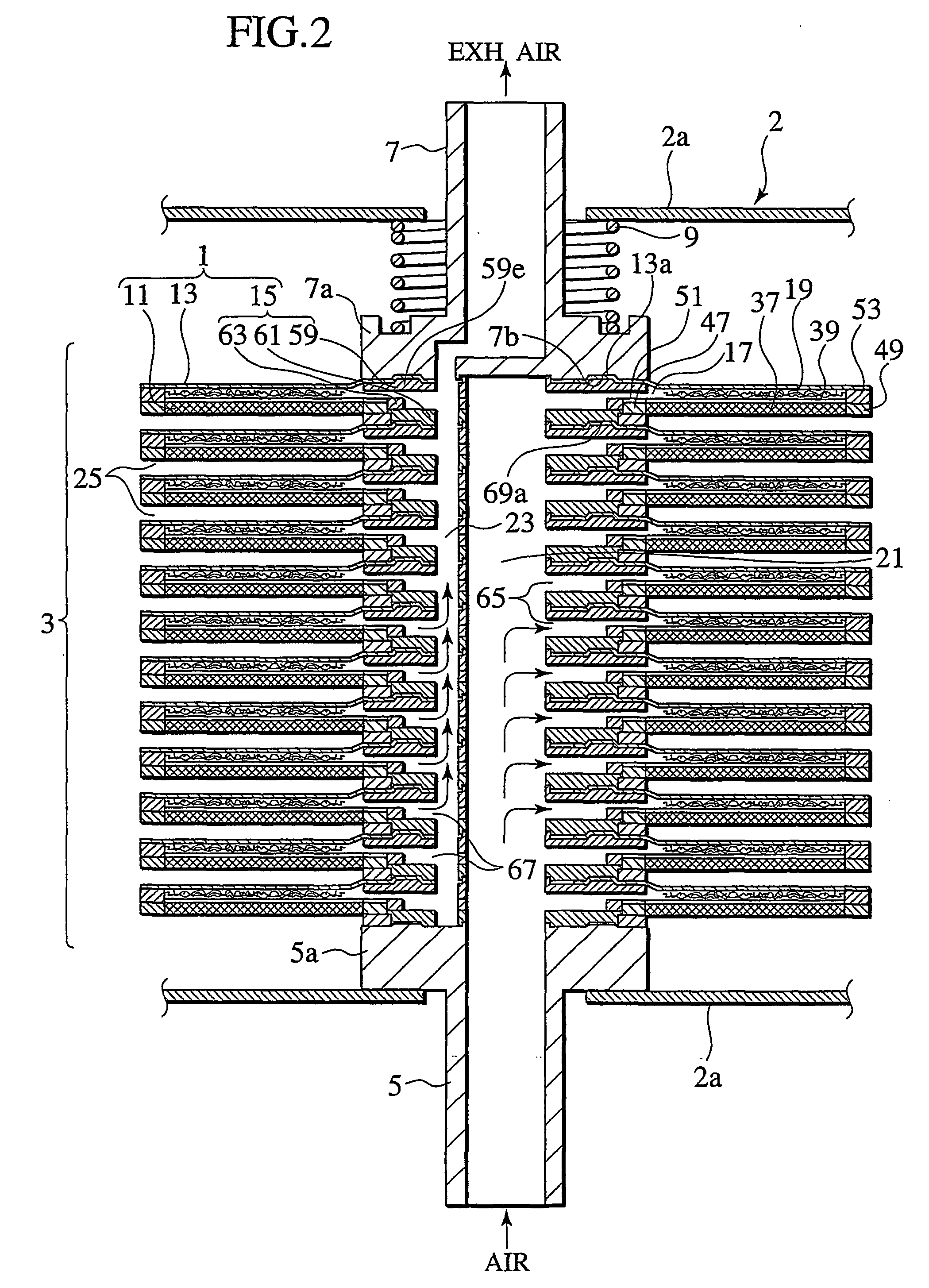
[0025]FIG. 1 is a perspective view of fuel cells (i.e., fuel cell stack) of this embodiment in a state accommodated within a casing. FIG. 2 is a schematic II-II cross-sectional view of the fuel cell stack in FIG. 1, showing an inner structure of the stack viewed from a direction perpendicular to a stacking direction of the stack, so as to show a gas supplying conduit 5 and its associated constitution mainly at the right side and a gas exhausting conduit 7 and its associated constitution mainly at the left side. FIG; 3 is a partially enlarged cross-sectional view of the fuel cell stack of FIG. 2, enlargingly showing a cell plate and a gas separator in the stack, mainly, at an inner peripheral side and an outer peripheral side of the disk-like constitution thereof, while omitting intermediate portions of the cell plate and gas...
second embodiment
[0082] Next, there will be described hereinafter a fuel cell of a second embodiment according to the present invention in detail, mainly with reference to FIG. 12. While the first embodiment has been constituted to exhaust the air as an oxidative gas from the gas supplying conduit 5 at the lower side to the gas exhausting conduit 7 at the upper side in FIG. 1, this second embodiment is mainly differentiated therefrom in that the air supplied to gas supplying holes 73 formed at the centers of holder members 150 is discharged from outer peripheral sides of cell units 10. Thus, the second embodiment will be described by emphasizing such a difference, while using like reference numerals for the identical constitutions and appropriately omitting or simplifying the explanation thereof.
[0083]FIG. 12 is a cross-sectional view of the fuel cell stack of this embodiment, showing a constitution exemplarily including two stages of cell units 10.
[0084] As shown in FIG. 12, each cell unit 10 inc...
third embodiment
[0093] Next, there will be described hereinafter a fuel cell of a third embodiment according to the present invention in detail, mainly with reference to FIG. 13. This third embodiment is mainly differentiated from the second embodiment in that the third embodiment is constituted such that hydrogen gas as a fuel gas is supplied to a fuel supplying channel 79 provided at a center of a holder member 150A, then through a fuel gas passage 250A under each cell plate 110A, and then discharged from an outer peripheral side of a cell unit 10A, similarly to air as an oxidative gas. Thus, the third embodiment will be described by emphasizing such a difference, while using like reference numerals for the identical constitutions and appropriately omitting or simplifying the explanation thereof.
[0094]FIG. 13 is a cross-sectional view of the fuel cell stack of this embodiment, showing a constitution exemplarily including two stages of cell units 10A.
[0095] As shown in FIG. 13, each cell unit 10...
PUM
 Abstract
Description
Claims
Application Information