Trigger system for small arms

a technology for small arms and triggers, applied in small arms, weapons, breech mechanisms, etc., can solve the problem of some high force expenditure, and achieve the effect of shortening the trigger movement, and reducing the force expenditur

Inactive Publication Date: 2006-02-16
T SWISS ARMS TECH
View PDF4 Cites 0 Cited by
  • Summary
  • Abstract
  • Description
  • Claims
  • Application Information

AI Technical Summary

Benefits of technology

[0008] The way in which the trigger system according to the invention operates corresponds to that of a Double Action Only trigger system placed under partial tension. By repetition (manually or by holding the trigger back after the first shot has been taken), the trigger system comes to an operating position under partial tension, in which the stored energy of the strike-hammer spring applied to the hammer is not yet sufficient to fire a cartridge. By activating the trigger, the hammer can first be placed under additional tension and then released to trigger a shot. Through a first locking edge of the trigger bar and the associated first fire-locking element of the hammer, the trigger system can be activated, on the basis of the favorable leverage, about the center of rotation of the hammer with a small force expenditure. After the first shot, however, there is also the possibility that the trigger system, through the second locking edge on the trigger bar and the associated second fire-locking element, can be activated with significantly shorter trigger movement, though with a somewhat higher expenditure of force. When the trigger bar is moved in the direction that releases the hammer, the second locking edge can come into contact with the associated second fire-locking element sooner, and triggering of a shot is possible with shorter trigger travel. In this case, however, because of the unfavorable lever of the second locking edges and the second firing edge involved with respect to the center of rotation of the hammer, a somewhat high expenditure of force is required. With the aid of the second locking edge and the associated second firing edge, another activation of the trigger system is also possible after a firing failure, but then with a somewhat higher expenditure of force and a longer trigger travel.

Problems solved by technology

In this case, however, because of the unfavorable lever of the second locking edges and the second firing edge involved with respect to the center of rotation of the hammer, a somewhat high expenditure of force is required.

Method used


Image

  • Trigger system for small arms
  • Trigger system for small arms
  • Trigger system for small arms

Examples


Embodiment Construction

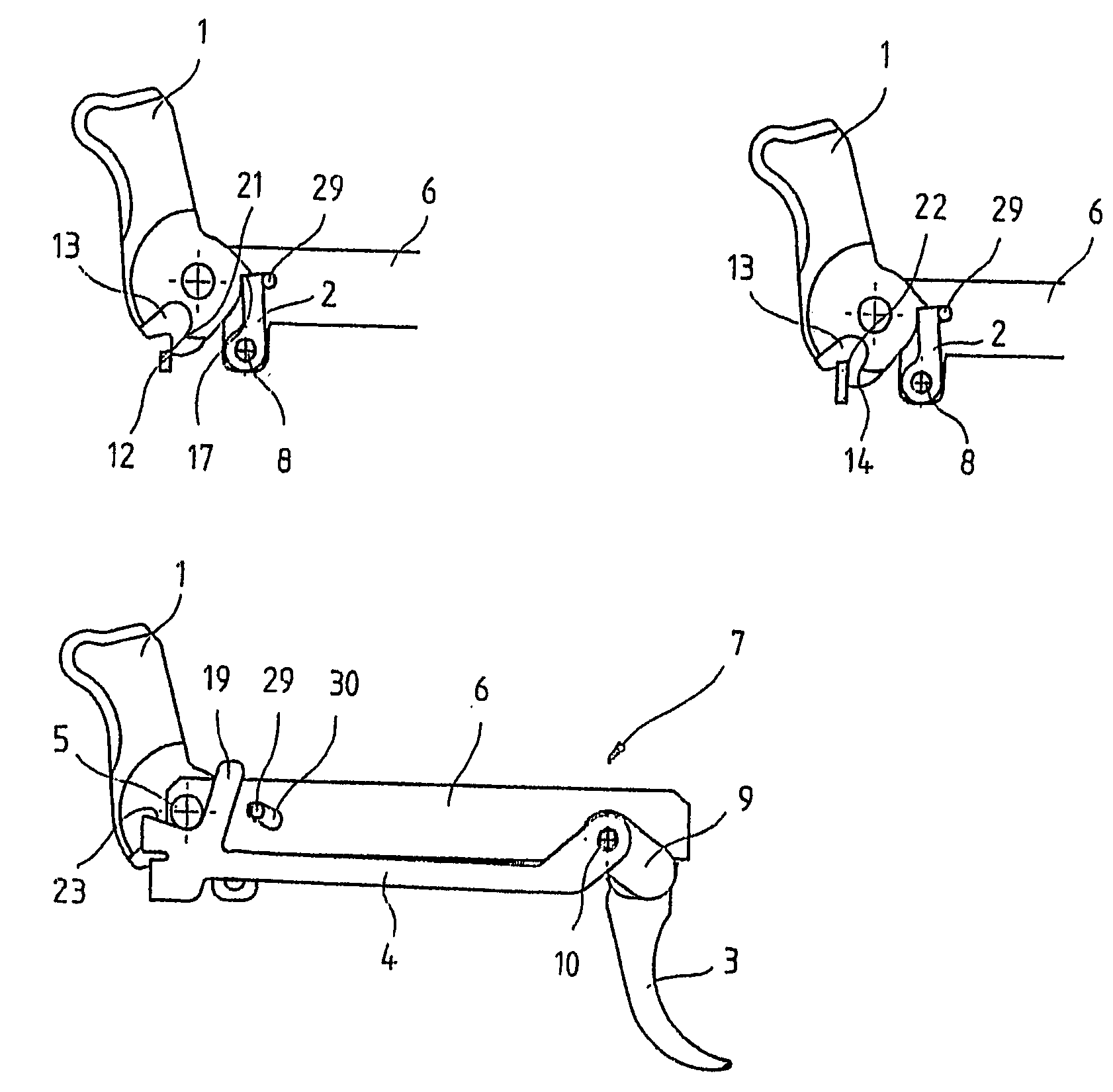
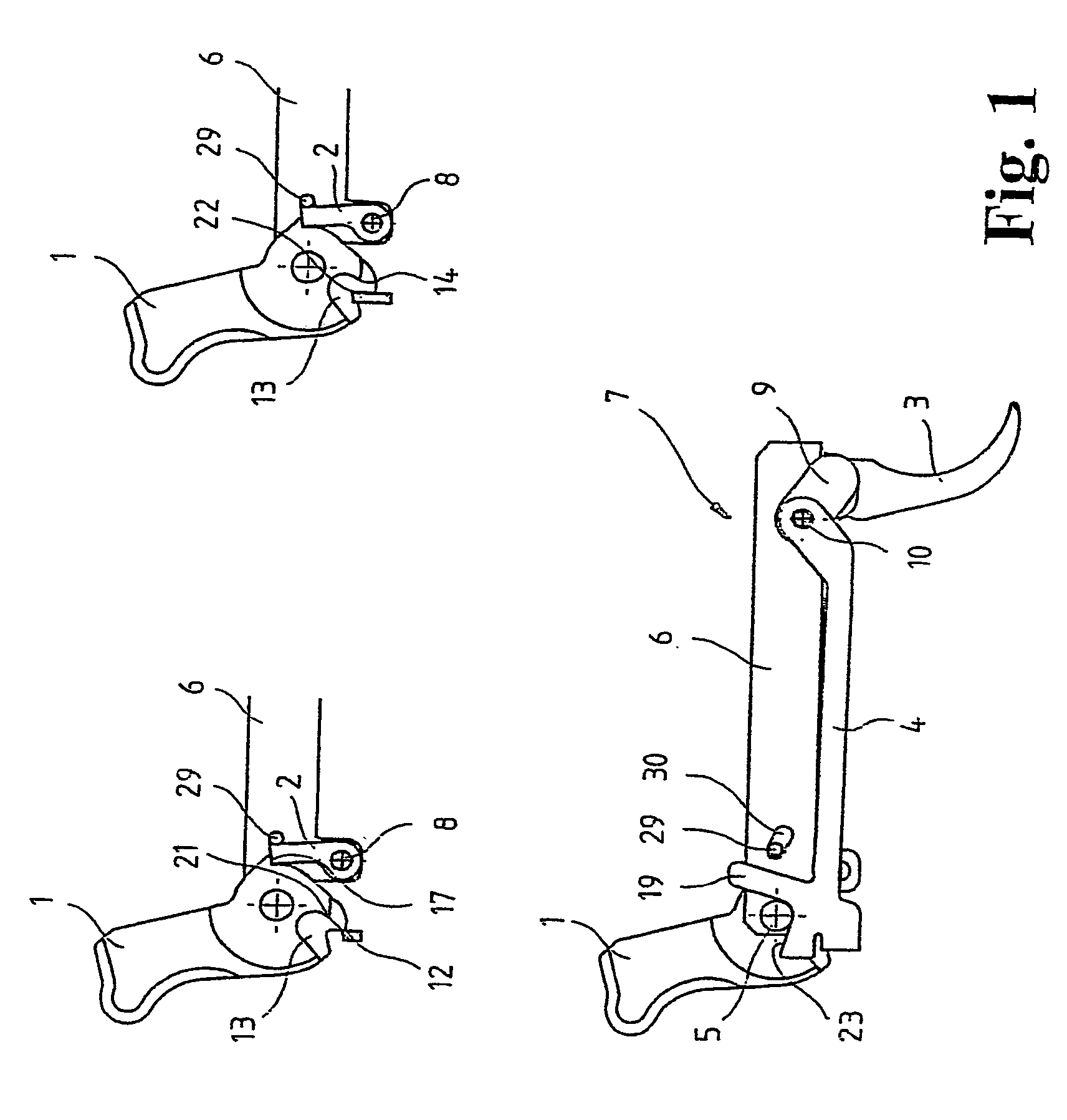
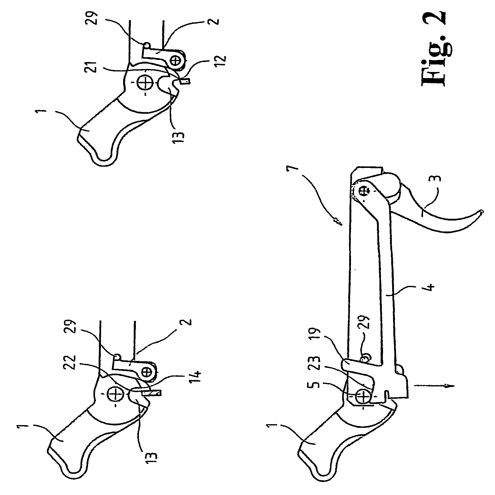
[0017] The trigger system for small arms shown schematically in FIGS. 1 through 4 contains a hammer 1 with a catch 2, a trigger 3 with a trigger bar 4 connected to it by a link, through which the hammer 1 is released during activation of the trigger 3, first being placed under tension against the force of a hammer spring (not shown), and then released to set off a shot. The trigger bar 4 is moved back by a trigger spring (not shown) that pushes the trigger 3 into a forward exit position and is likewise pushed up by a trigger-bar spring (not shown).

[0018] As can be seen from the lower illustration in FIG. 1, the hammer 1 is arranged so as to be movable about a hammer axis 5 between two side parts 6 of a carrier element 7 that are separated from each other by a gap. Between the two side parts 6 of the carrier element 7, a catch 2 is also mounted so as to be movable about a cross-pin 8. Through this catch 2, the hammer 1 is held in a position under partial tension, as will be explaine...


PUM


Abstract

The invention relates to a trigger system for small arms, said system including a hammer, a catch associated with the hammer, a trigger, and a trigger bar which co-operates with the trigger and has a first locking edge for engaging with a first fire locking element of the hammer. The aim of the invention is to create a trigger system which has a low trigger resistance and remains operable even in the event of firing failure. To this end, the trigger bar has a second locking edge for engaging with a second fire locking element of the hammer.

Description

CROSS-REFERENCE TO RELATED APPLICATION [0001] This application is a continuation of International Application No. PCT / EP2003 / 014587, filed Dec. 19, 2003, the contents of which are incorporated herein by reference.FIELD OF THE INVENTION [0002] The invention concerns a trigger system for small arms. BACKGROUND OF THE INVENTION [0003] So-called Double Action Only trigger systems are already known as pure tension triggers, in which the hammer must first be placed under tension by the trigger for each shot. Through such trigger systems, high safety is provided for the weapon, since it can be stored or laid aside without an additional release of tension. However, conventional Double Action Only trigger systems have uniform trigger travel and a relatively high trigger resistance. [0004] There are also trigger systems that are already partly under tension and have shorter trigger travel and make it possible to set off a shot with low trigger resistance. Often, however, a second pull is not ...

Claims


Application Information

Patent Timeline
Patent Type & Authority Applications(United States)
IPC IPC(8): F41A3/00F41A19/48
CPCF41A19/48
Inventor KELLERMANN, HARALD
Owner T SWISS ARMS TECH
Why Eureka
Try Eureka