
Milking Unit for Milking an Animal

a technology for milking units and animals, applied in milking devices, dairy products, applications, etc., can solve the problems of limited freedom of choice in construction materials, limited freedom of construction materials, and the risk of the milk hose falling off the connector during milking, etc., to achieve the effect of high force expenditure, simple manner, and well-sealed connection

Active Publication Date: 2014-05-22
GEA FARM TECH
View PDF0 Cites 0 Cited by
  • Summary
  • Abstract
  • Description
  • Claims
  • Application Information

AI Technical Summary

Benefits of technology

The patent text describes a new design for a milk hose that allows for easy connection to a milking unit and improved hygiene and maintenance. The hose is made from a soft material in the middle, with solid materials at the ends for connection. This design allows for separate replacement of the worn teat rubber, while keeping the milk hose usable. This results in cost and resource conservation. Additionally, the use of different materials provides different advantages such as long lifetime for the silicone and rubber.

Problems solved by technology

If this is not the case, then there is the risk of the milk hose slipping off the connector during milking.
Once a milk hose has slipped off during milking, it can be mounted onto the connector only with considerable mounting effort.
The adhesion is essentially determined by the connector / milk hose material pairing, such that the freedom of choice with regard to the constructional materials is limited.
The teat rubber is subject to wear, such that it is necessary to replace the configuration—known as a monobloc—of the one-piece teat rubber with the milk hose, such that the milk hose is also removed from the milk collecting component.
The frustoconical configuration of the coupling element also results in a self-centering of the milk hose at the coupling element when it is slipped over the coupling element.

Method used


Image

  • Milking Unit for Milking an Animal
  • Milking Unit for Milking an Animal
  • Milking Unit for Milking an Animal

Examples


Embodiment Construction

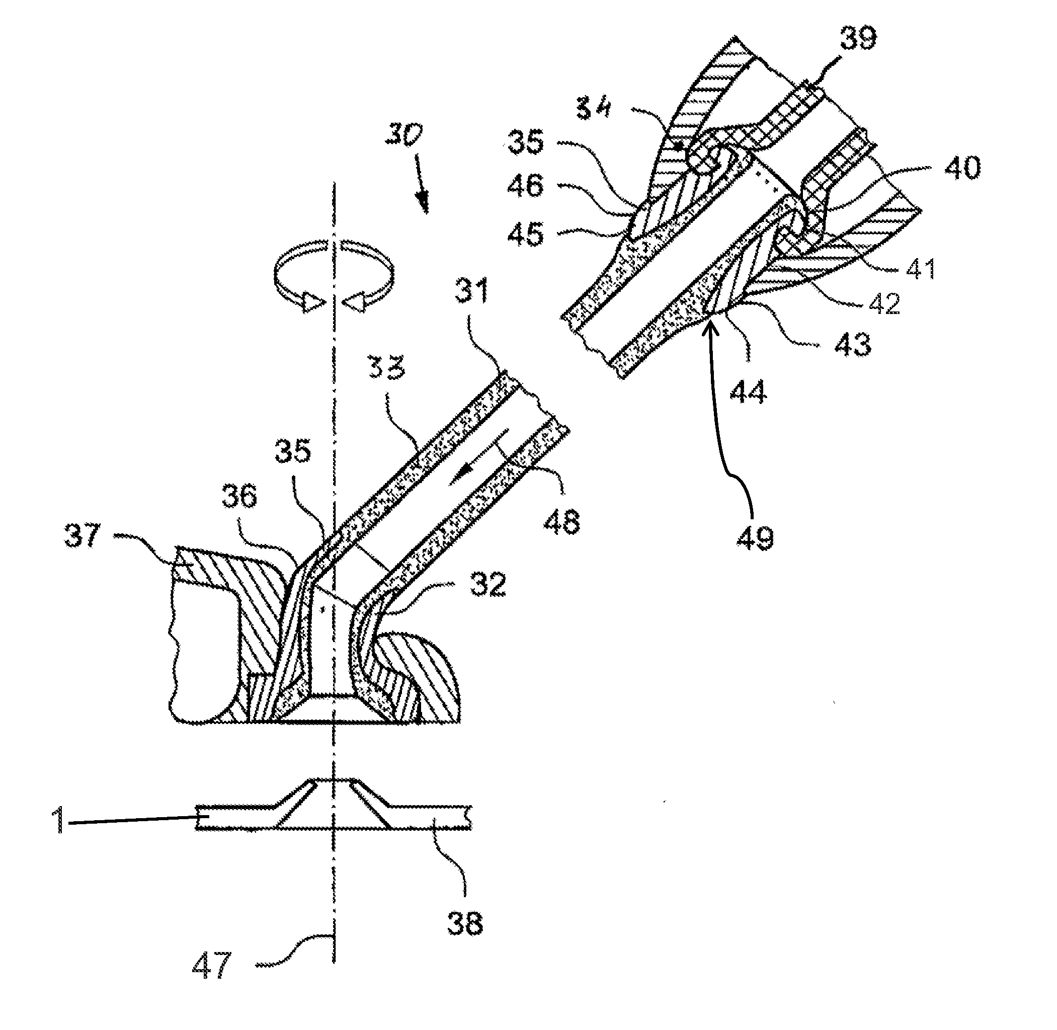
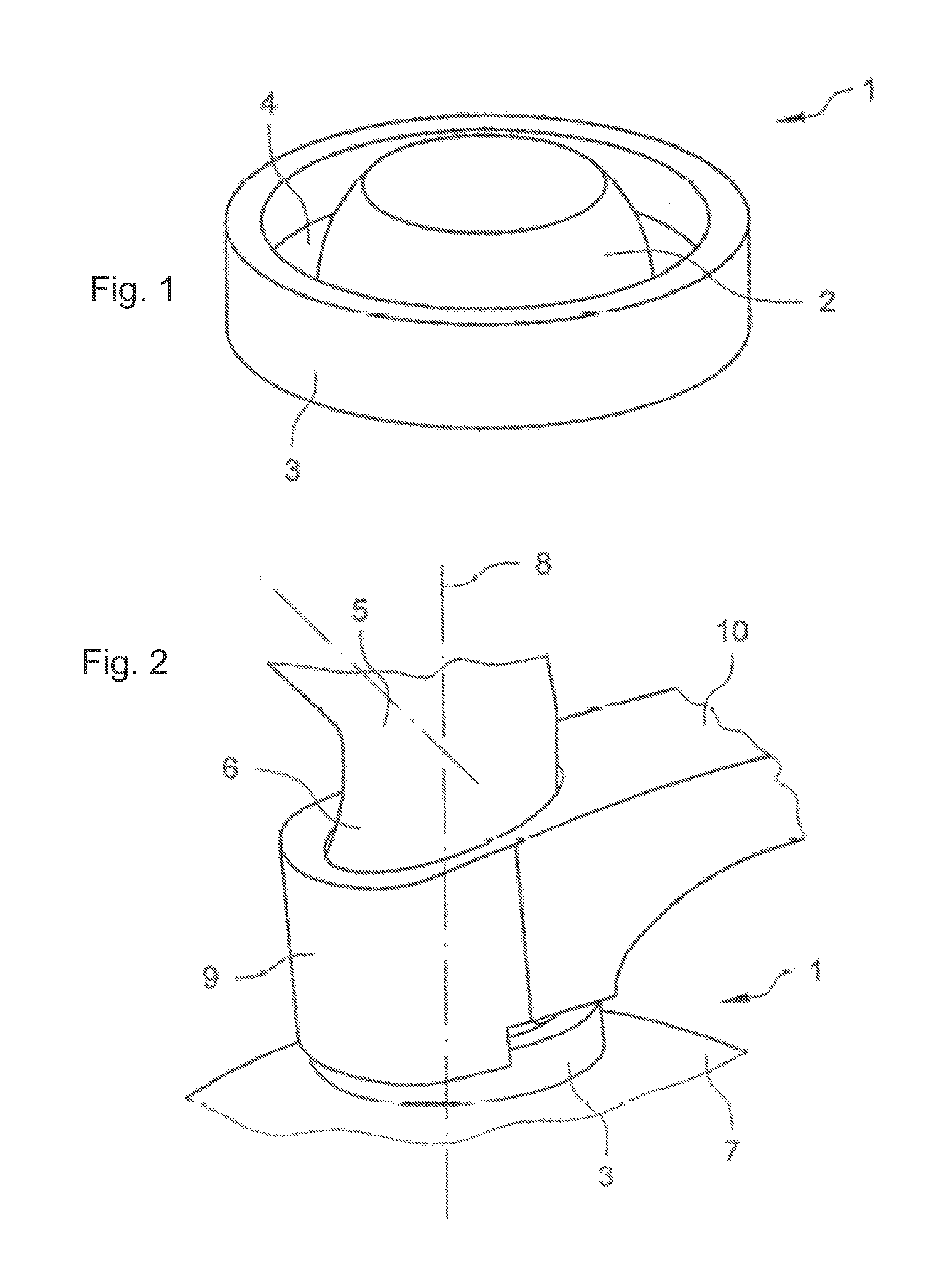
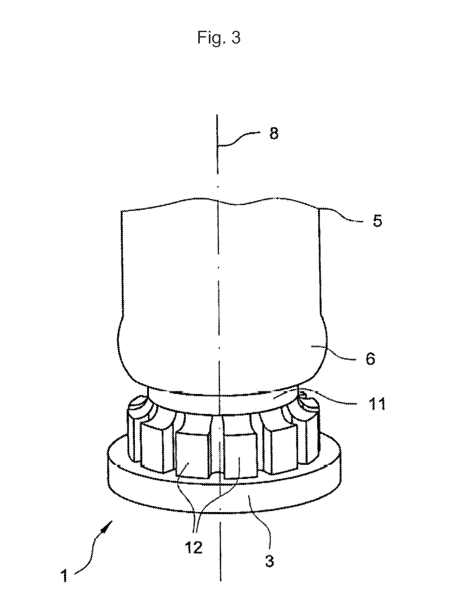
[0066]FIG. 1 illustrates a coupling element 1 in a perspective view. The coupling element 1 illustrated therein can be formed at the milk collecting component and / or milking cup. At the milking cup, the coupling element can be provided either at the teat rubber or at a milking cup sleeve. The coupling element can be an integral part for example of a cover of a milk collecting component.

[0067]Although essentially the connection of a milk hose to a milk collecting component is described below, a connection can also be correspondingly formed between a milking cup and a milk hose.

[0068]The coupling element 1 has a frustoconical section 2. The frustoconical section 2 is formed in such a way that it can be introduced into an end section of a milk hose.

[0069]A wall 3 surrounding the frustoconical section 2 is provided at a distance from the base of the frustoconical coupling element 1. The wall 3 is connected to the frustoconical section 2 via a bottom 4. The distance between the wall 3 an...


PUM


Abstract

A milking unit is proposed, comprising at least one milk hose, having a first end section and a second end section, and a milk collecting component, which is connected to the first end section of the milk hose. The milk collecting component has at least one coupling element, which cooperates with the first end section of the milk hose. A clamping element is provided, which cooperates with the coupling element so that an essentially fluid-tight connection is generated between the milk hose and the milk collecting component.

Description

[0001]This application is a divisional of U.S. application Ser. No. 12 / 152,076, filed May 12, 2008, which claims the benefit of German Application No.: DE 102007022803.3-23, filed May 11, 2007, each of which is incorporated herein by reference in their entireties.FIELD AND BACKGROUND OF THE INVENTION[0002]The subject matter of the invention relates to a milking unit comprising at least one milk hose having a first end section and a second end section, and a milk collecting component, which is connected to the first end section of the milk hose, a milking unit comprising a milk hose having a first end section and a second end section, and a milking cup having a teat rubber and a milking cup sleeve, the milking cup being connected to the second end section of the milk hose, and a milking unit comprising at least one milk hose having a first end section and a second end section, a milk collecting component, which is connected to the first end section of the milk hose, and at least one ...

Claims


Application Information

Patent Timeline
Patent Type & Authority Applications(United States)
IPC IPC(8): A01J5/04
CPCA01J5/044
Inventor AUBURGER, MARKUSORBAN, THOMAS
Owner GEA FARM TECH
Learn More