Electric drive unit for motor vehicle

A technology for electric drive units and motor vehicles, which is applied to the arrangement of cooling combination of power devices, mechanical equipment, power devices, etc. It can solve problems such as difficulties in the lubrication process, achieve smooth flow, and improve the effect of oil extraction

Pending Publication Date: 2022-03-18
BPW BERGISCHE ACHSEN KOMMANDITGES
View PDF0 Cites 0 Cited by
  • Summary
  • Abstract
  • Description
  • Claims
  • Application Information

AI Technical Summary

Problems solved by technology

In the case of jet lubrication, such pools make it difficult to achieve an ideal lubrication process
Especially in the area of ​​the oil circulation, it can be difficult to pump the oil, because due to the rotation, the oil flows at a high flow rate over the provided oil outlet opening instead of completely entering the oil outlet opening

Method used


Image

  • Electric drive unit for motor vehicle
  • Electric drive unit for motor vehicle
  • Electric drive unit for motor vehicle

Examples


Embodiment Construction

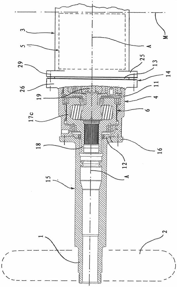
[0031] figure 1 A schematic illustration shows half of an electric drive shaft for a motor vehicle. The shown half of the drive shaft is used to drive the figure 1 Wheel 2 is shown with a dotted line on the left edge. The second half of the same design of the drive shaft is located symmetrically on the figure 1 The other side of the mid-plane M of the vehicle drawn in and supports the corresponding wheel on the other side of the vehicle. The electric drive shaft is in its entirety a continuous rigid shaft from one vehicle side to the other.

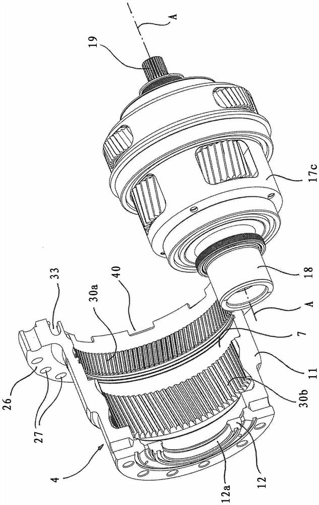
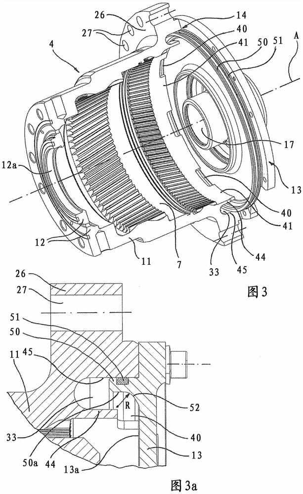
[0032] For each vehicle side and for driving the respective wheel 2 , an electric drive 5 , in particular an electric motor, is arranged in the vicinity of the mid-plane M of the vehicle. Downstream of each electric motor toward the exterior of the vehicle is a transmission 6 , here in the form of a two-stage planetary transmission.

[0033] The two electric drives are located in a common motor housing 3 , which can be one-piece or m...


PUM


Abstract

The invention relates to an electric drive unit for a motor vehicle. The invention relates to an electric drive unit for a motor vehicle, comprising an electric drive (5), a transmission (6) which is arranged downstream of the electric drive (5) in the direction of a force transmission flow and which is arranged in a transmission housing (4), a device for circulating a cooling liquid in an interior (7) of the transmission housing (4), and a rotatably arranged input or output shaft (19, 18) of the transmission (6), according to the invention, the transmission housing (4) consists of a housing peripheral wall (11) annularly surrounding a central axis (A) and an end wall (13), and the end wall (13) extends radially outward from an opening (17) for the input or output shaft (19, 18) to a connecting region (14) in which the end wall (13) and the housing peripheral wall (11) are connected to each other. In order to improve the flow state by means of structural measures, in particular in the region of the transmission housing in which the coolant is discharged or withdrawn from the transmission in the region of the coolant circulation, an annular chamber (33) is provided which extends in the circumferential direction along a connecting region (14) and which is connected to the interior (7) via a separate opening (40).

Description

technical field [0001] The invention relates to an electric drive unit for a motor vehicle, having an electric drive, a transmission arranged downstream of the electric drive in the direction of the power transmission flow and arranged in a transmission housing, for cooling in the interior of the transmission housing A device for fluid circulation and a rotatably arranged input or output shaft of a transmission, wherein the transmission housing consists of a housing peripheral wall annularly surrounding the central shaft and an end wall, and the end wall is drawn from a shaft for the input or output shaft The opening extends radially outwards as far as the connecting region, in which the end wall and the housing peripheral wall are connected to each other. Background technique [0002] Such an electric drive unit is used as a vehicle drive. Such an electric drive unit is preferably used as a component of an electric drive axle for a commercial vehicle. In this type of cons...

Claims


Application Information

Patent Timeline
Patent Type & Authority Applications(China)
IPC IPC(8): B60K17/04B60K1/00B60K11/02F16H57/04
CPCB60K17/046B60K1/00B60K11/02F16H57/0409F16H57/0412B60K2001/001B60K2001/003F16H57/04B60K2001/006
Inventor D·布伦纳U·施泰纳
Owner BPW BERGISCHE ACHSEN KOMMANDITGES
Why Eureka
Try Eureka