Device and method for making and using a pipe coupling device

Inactive Publication Date: 2007-11-08
JIMENEZ ANDREW
View PDF12 Cites 39 Cited by
  • Summary
  • Abstract
  • Description
  • Claims
  • Application Information

AI Technical Summary

Benefits of technology

[0007] An objective of the present invention is to provide a self seating colle

Problems solved by technology

The disadvantage with these conventional pipe coupling devices is that the pipes being linked together are oftentimes deformed as a consequence of the non-uniform clamping force applied by conventional devices.
Thus, it was not always possible to reuse these coupling devices and/or the pipes that were being joined together.
Atte

Method used


Image

  • Device and method for making and using a pipe coupling device
  • Device and method for making and using a pipe coupling device
  • Device and method for making and using a pipe coupling device

Examples


Embodiment Construction

[0038] Particular embodiments of the present invention will now be described in greater detail with reference to the figures.

[0039] This invention overcomes the conventional problems described above by providing a pipe coupling device that evenly distributes a circumferential fastening force to secure two pipes to each other in a manner that permits a user to quickly and easily assemble and disassemble a pipe joint.

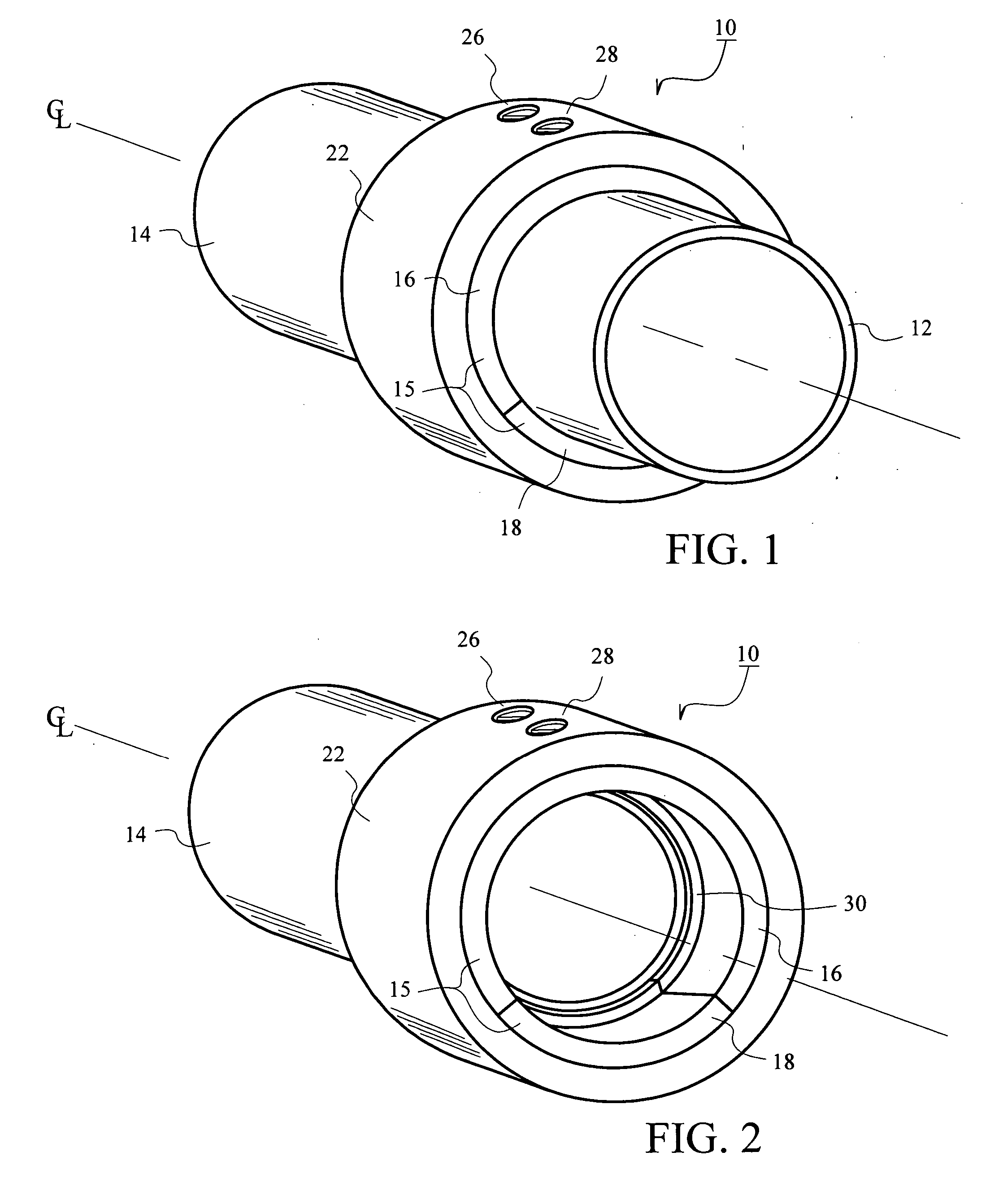
[0040]FIG. 1 is a perspective view illustrating a pipe coupling device 10 securing a first pipe 12 to a second pipe 14. FIG. 2 further illustrates the pipe coupling device 10 without the obstructed view of the first pipe 12.

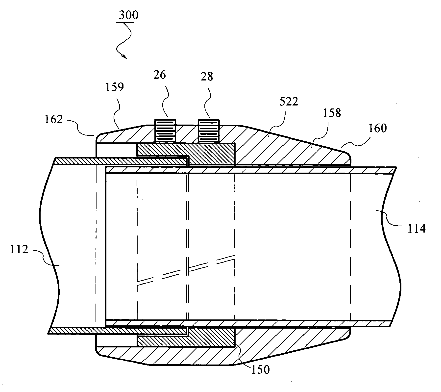
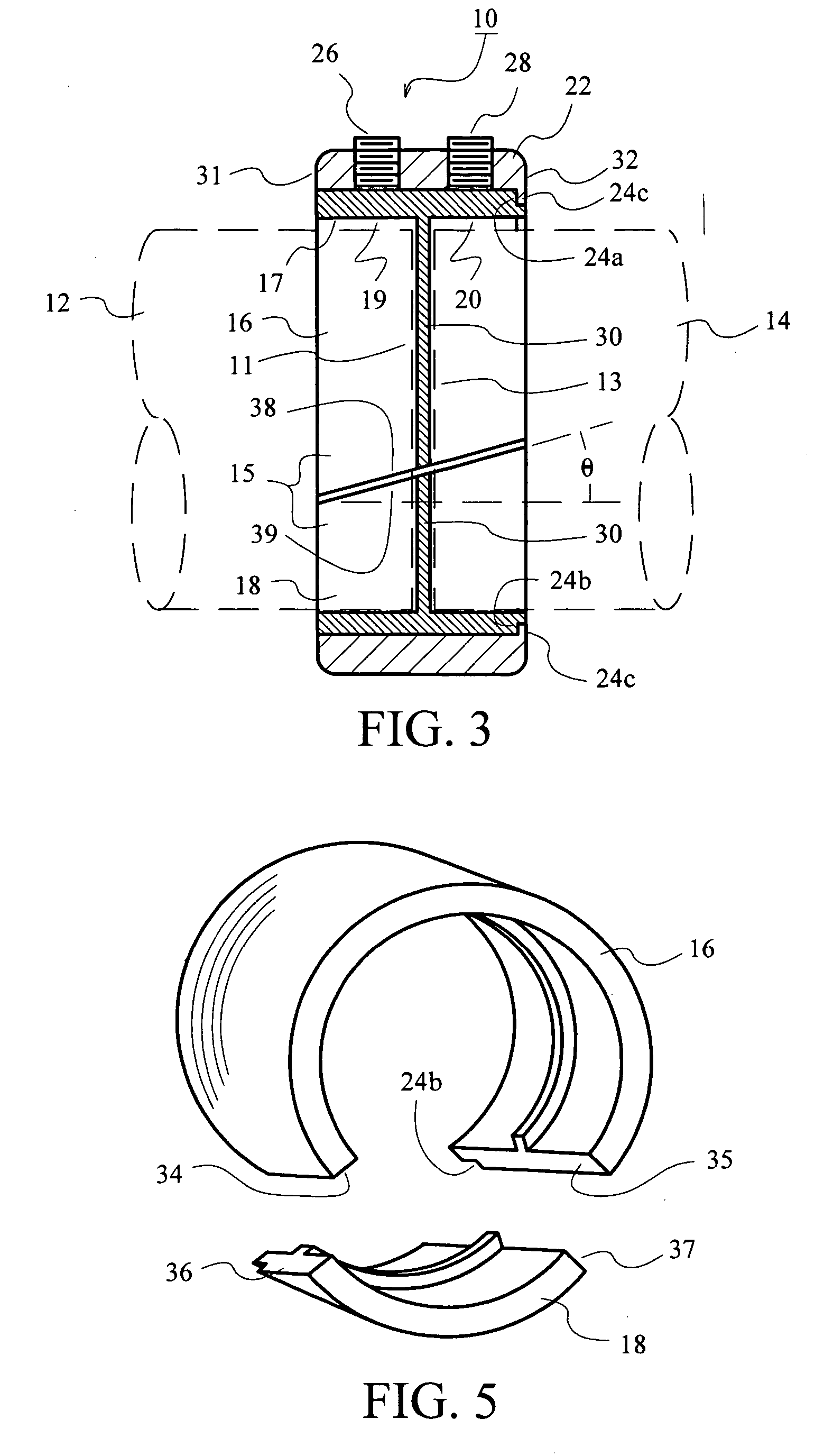
[0041]FIG. 3 illustrates a first exemplary embodiment of the invention. As shown, the pipe coupling device 10 includes a collar 22, a first set screw 26, a second set screw 28 and a collet 15. The collet 15 is composed of a first collet portion 16 and a second collet portion 18 recessed within the collar 22. The first set screw 26 and the second set...


PUM


Abstract

A pipe coupling device that secures a first pipe to a second pipe. The pipe coupling device includes a collet disposed within a collar having a fastening mechanism. The collet includes a first collet portion that interlocks with a second collet portion to form a seal that fastens the first pipe securely to the second pipe.

Description

CROSS REFERENCE TO RELATED APPLICATION [0001] This application is a Non-Provisional Application which claims the benefit of the filing date of U.S. Provisional Application Ser. No. 60 / 579,186, entitled “360 DEGREE ANNULATED SELF SEATING EXHAUST COLLET” filed May 9, 2005, the entirety of which is incorporated herein by reference.BACKGROUND OF THE INVENTION [0002] 1. Field of the Invention [0003] The present invention relates in general to a pipe coupling device that secures a first pipe to a second pipe, and in particular to providing an evenly distributed circumferential fastening force to seal and secure the two pipes to each other. [0004] 2. Description of the Related Art [0005] Numerous pipe coupling devices are currently available on the market today. This art has shown that many of the commercially available pipe coupling devices are devised from a plethora of various coupling mechanisms, including using straps to brace two pipes adjacent to each other. [0006] The disadvantage ...

Claims


Application Information

Patent Timeline
IPC IPC(8): F16L27/12F16L21/00
CPCF16L25/065
Inventor JIMENEZ, ANDREW
Owner JIMENEZ ANDREW
Why Eureka
Try Eureka