Device and method for making and using a pipe coupling device

a pipe coupling and pipe technology, applied in the direction of couplings, screw threaded joints, mechanical equipment, etc., can solve the problems of not always being able to reuse the coupling device and/or the pipe that was being joined together, and the pipe being linked together is often deformed, so as to achieve the effect of minimizing the disfigurement of two pipes

Inactive Publication Date: 2010-06-15
JIMENEZ ANDREW
View PDF19 Cites 11 Cited by
  • Summary
  • Abstract
  • Description
  • Claims
  • Application Information

AI Technical Summary

Benefits of technology

[0007]An objective of the present invention is to provide a self seating collet which is adapted to minimize disfigurement of two pipes being joined together.
[0008]Another object of this invention is to provide an easy to use modular pine coupling device that is simple and quick to assemble and disassemble.
[0014]Unlike other conventional clamps developed for vehicle exhaust systems, this invention is not invasive and / or mechanically intrusive to the pipes joined together. Accordingly, improved longevity and ease of interchangeability is one of the benefits of this invention. Furthermore, superior sealing surface effects are attained from this invention.
[0015]According to this invention, the amount of force delivered by the clamp is high, yet, the amount of torque needed to tighten the first collet portion and the second collet portion to the pipes is low. Therefore, the risk of personal injury is reduced.
[0016]This concept is modular and interchangeability is an advantage. A sub-component in a linkage system of numerous pipes of varying sizes may be efficiently exchanged with ease in accordance with this invention with no affect to the remaining sub-components in the linkage system. Accordingly, different pipe sizes that need to be coupled to each other can be easily accommodated.

Problems solved by technology

The disadvantage with these conventional pipe coupling devices is that the pipes being linked together are oftentimes deformed as a consequence of the non-uniform clamping force applied by conventional devices.
Thus, it was not always possible to reuse these coupling devices and / or the pipes that were being joined together.
Attempts have been made in the past to effectively fasten two pipes together without causing deformation to the pipes, however, there has been little success.
Furthermore, the conventional pipe coupling devices fail to secure the two pipes in a manner in which a securing force is evenly distributed circumferentially onto the pipes.

Method used


Image

  • Device and method for making and using a pipe coupling device
  • Device and method for making and using a pipe coupling device
  • Device and method for making and using a pipe coupling device

Examples


Embodiment Construction

[0038]Particular embodiments of the present invention will now be described in greater detail with reference to the figures.

[0039]This invention overcomes the conventional problems described above by providing a pipe coupling device that evenly distributes a circumferential fastening force to secure two pipes to each other in a manner that permits a user to quickly and easily assemble and disassemble a pipe joint.

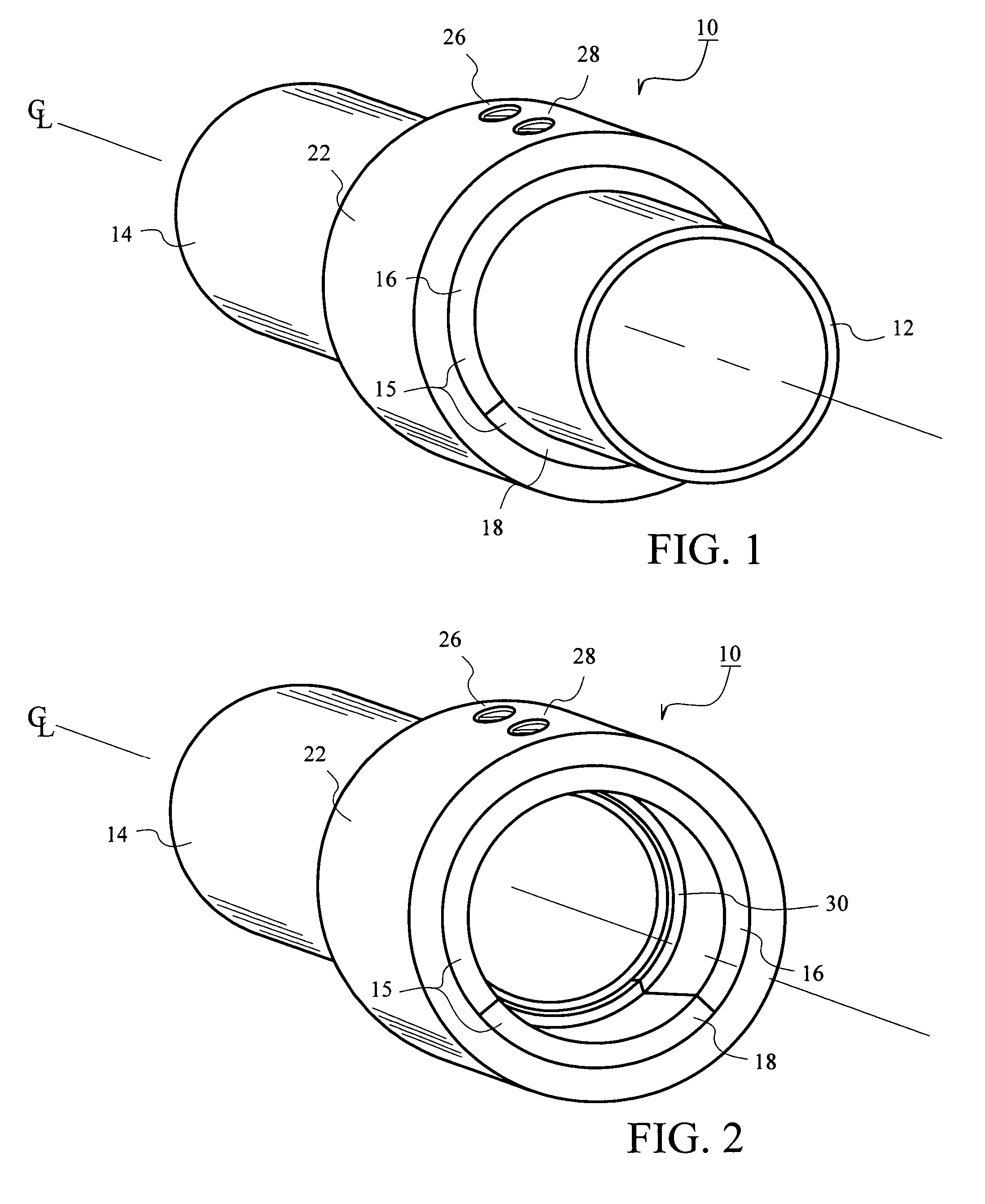
[0040]FIG. 1 is a perspective view illustrating a pipe coupling device 10 securing a first pipe 12 to a second pipe 14. FIG. 2 further illustrates the pipe coupling device 10 without the obstructed view of the first pipe 12.

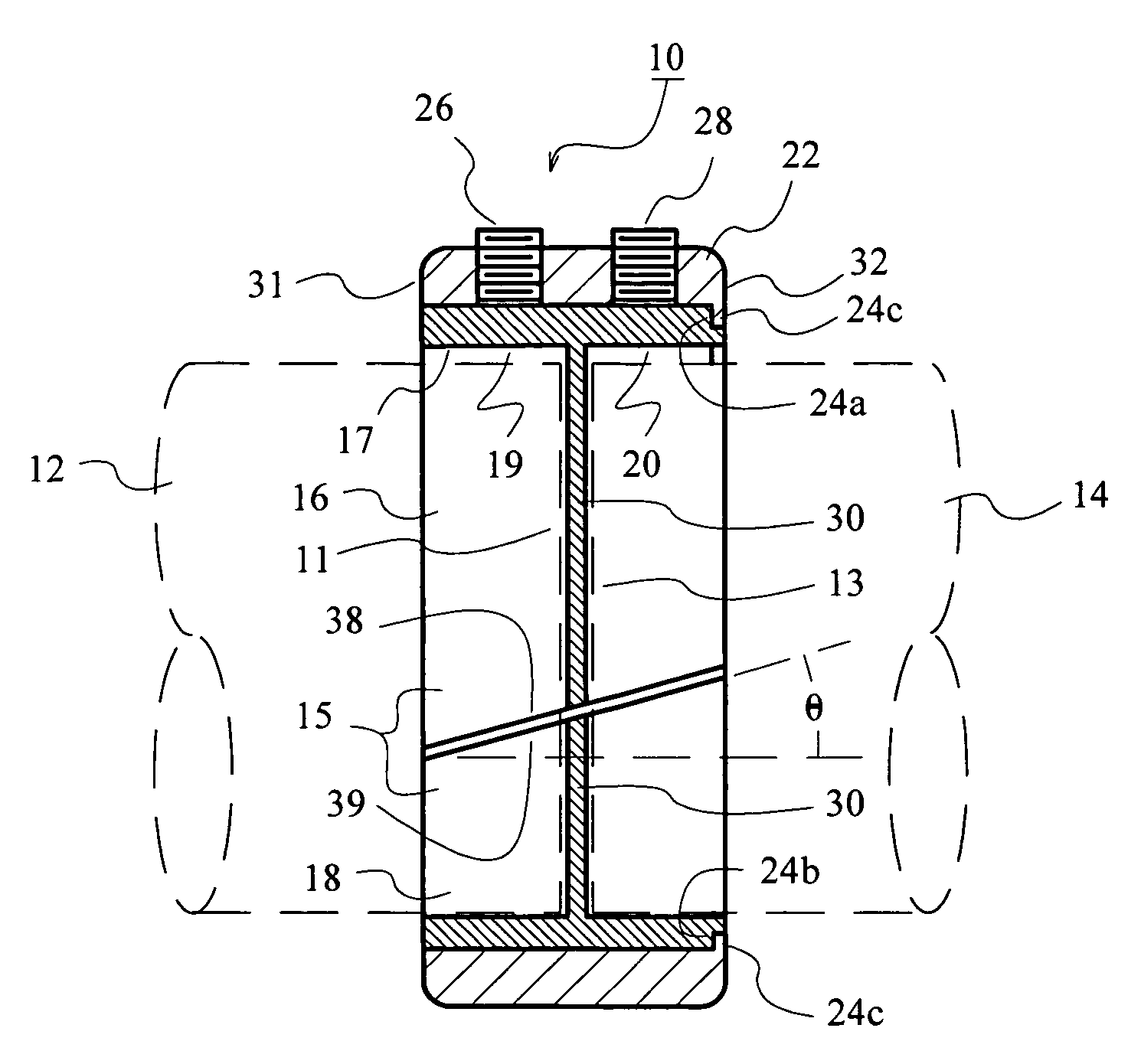
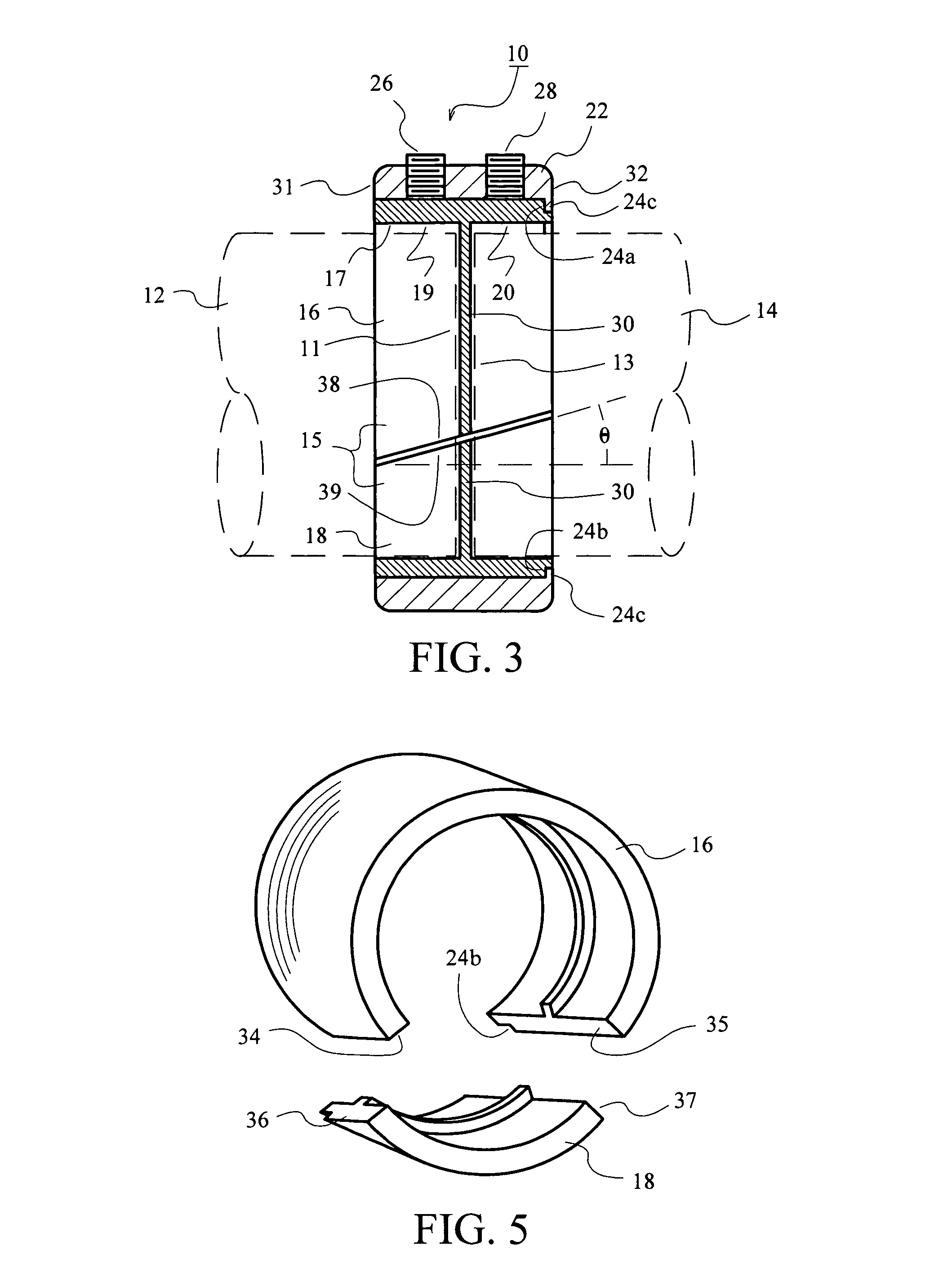
[0041]FIG. 3 illustrates a first exemplary embodiment of the invention. As shown, the pipe coupling device 10 includes a collar 22, a first set screw 26, a second set screw 28 and a collet 15. The collet 15 is composed of a first collet portion 16 and a second collet portion 18 recessed within the collar 22. The first set screw 26 and the second set scre...


PUM


Abstract

A pipe coupling device that secures a first pipe to a second pipe. The pipe coupling device includes a collet disposed within a collar having a fastening mechanism. The collet includes a first collet portion that interlocks with a second collet portion to form a seal that fastens the first pipe securely to the second pipe.

Description

CROSS REFERENCE TO RELATED APPLICATION[0001]This application is a Non-Provisional Application which claims the benefit of the filing date of U.S. Provisional Application Ser. No. 60 / 679,186, entitled “360 DEGREE ANNULATED SELF SEATING EXHAUST COLLET” filed May 9, 2005, the entirety of which is incorporated herein by reference.BACKGROUND OF THE INVENTION[0002]1. Field of the Invention[0003]The present invention relates in general to a pipe coupling device that secures a first pipe to a second pipe, and in particular to providing an evenly distributed circumferential fastening force to seal and secure the two pipes to each other.[0004]2. Description of the Related Art[0005]Numerous pipe coupling devices are currently available on the market today. This art has shown that many of the commercially available pipe coupling devices are devised from a plethora of various coupling mechanisms, including using straps to brace two pipes adjacent to each other.[0006]The disadvantage with these c...

Claims


Application Information

Patent Timeline
Patent Type & Authority Patents(United States)
IPC IPC(8): F16L21/06F16L21/08
CPCF16L25/065
Inventor JIMENEZ, ANDREW
Owner JIMENEZ ANDREW
Why Eureka
Try Eureka