
Aluminum heat exchanger and method of making thereof

a heat exchanger and aluminum technology, applied in the field of aluminum heat exchangers, can solve the problems of not optimizing the specific heat transfer (heat rejection/core weight) of efficient heat exchangers, and achieve the effects of minimizing manufacturing difficulty, reducing side pressure drop, and maximum performance in automotive applications

Inactive Publication Date: 2005-03-03
VALEO INC
View PDF16 Cites 41 Cited by
  • Summary
  • Abstract
  • Description
  • Claims
  • Application Information

AI Technical Summary

Benefits of technology

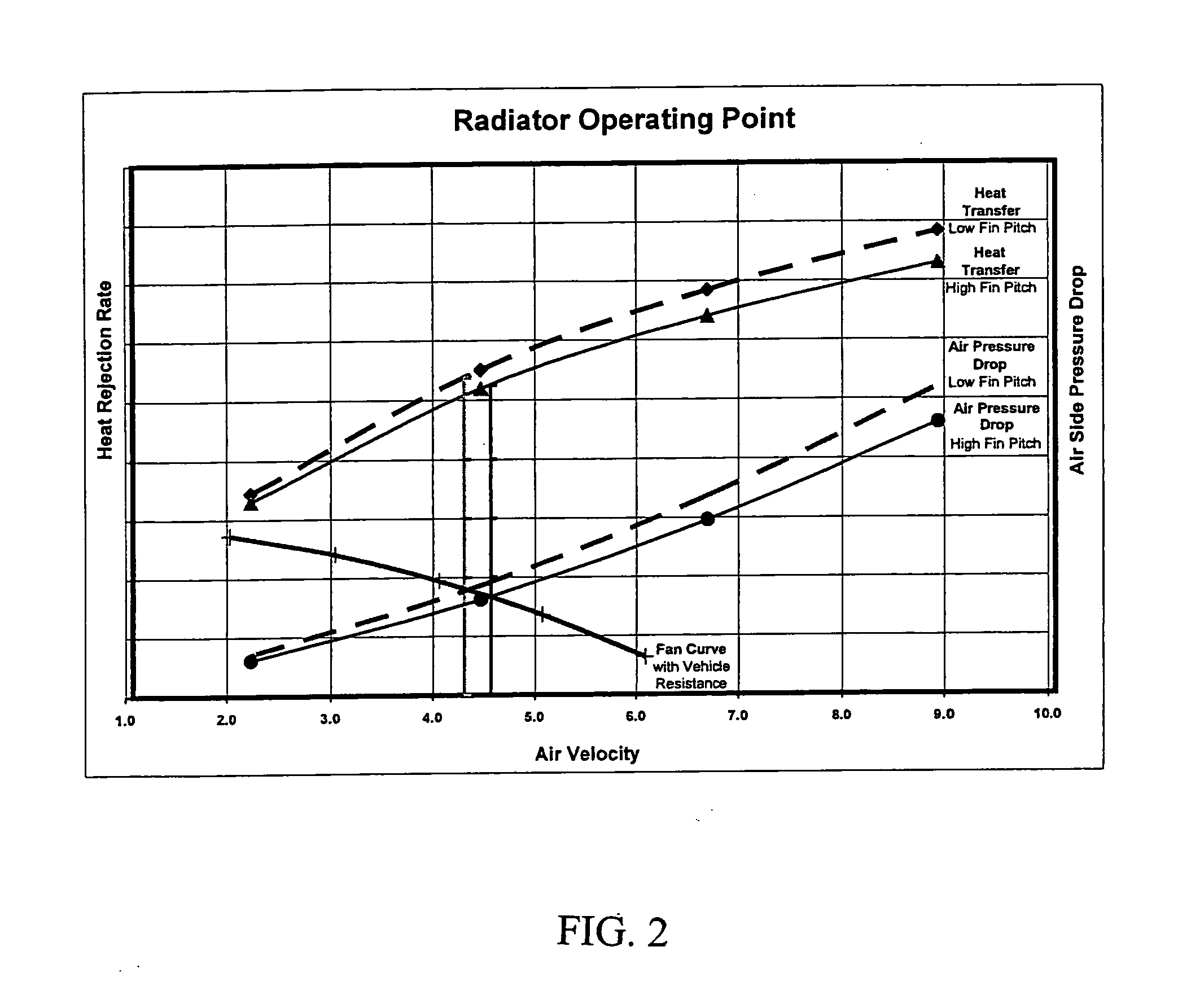
[0005] It is an object of the present invention to provide a heat exchanger, and, in particular, an aluminum-based heat exchanger, wherein the use of specific materials, weights, heights and thicknesses leads to fewer side pressure drop and other issues affecting the efficiency of exchangers. Therefore, it is a further object of the present invention to provide an aluminum heat exchanger that performs at optimized levels under normal conditions of use. It is a further object of the present invention to provide an aluminum heat exchanger that has maximum performance in automotive applications with minimized manufacturing difficulty. It is a further object of the present invention to provide a heat exchanger with optimized performance related to tube side or internal pressure drop. It is a further object of the present invention to provide a brazed aluminum heat exchanger with optimized parameters related to tube characteristics such as tube height and tube thickness. The present invention also provides for increased ability to standardize core tubes and fins for many different vehicle applications, thereby reducing production costs.

Problems solved by technology

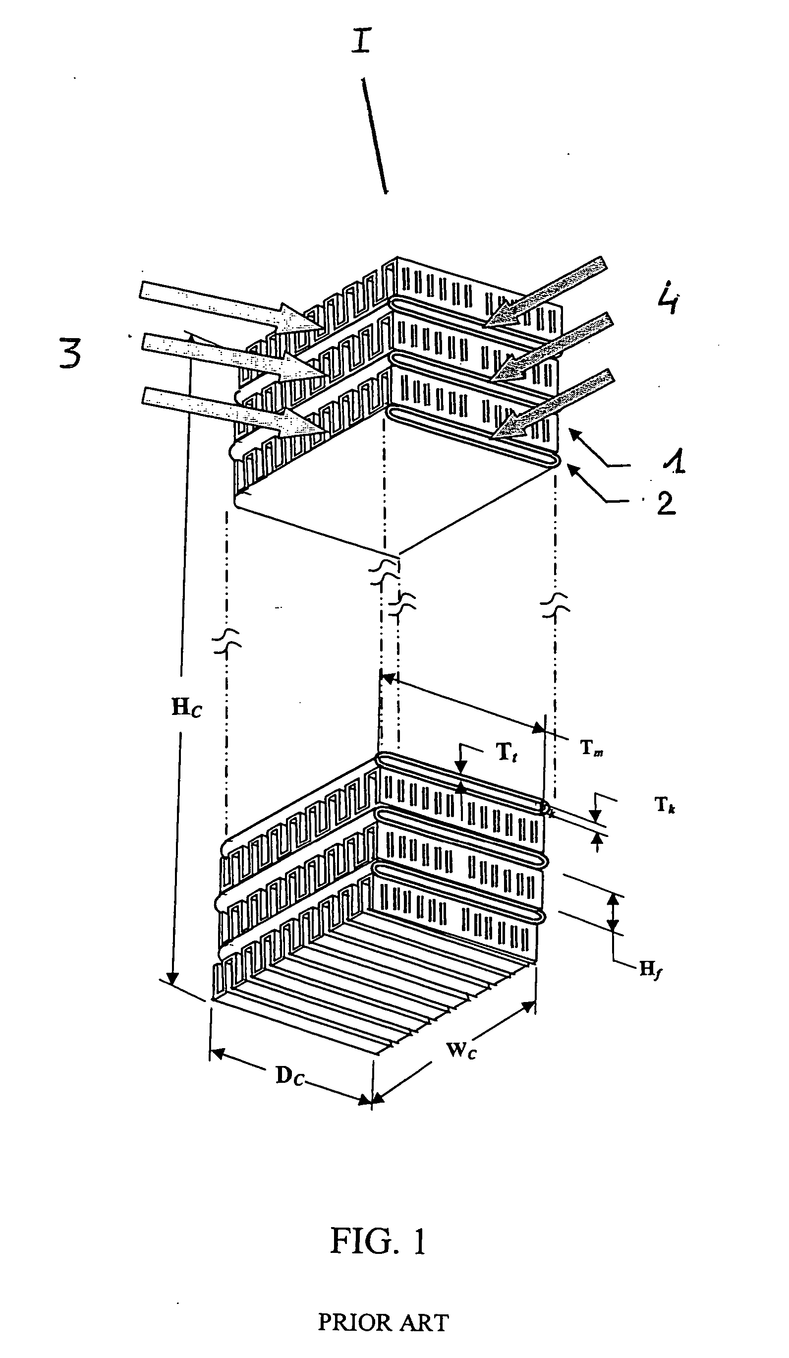
For example, prior art heat exchangers with tubes on 9.25 millimeter, as well as heat exchangers with 6.0 millimeter tube centers that have a higher air pressure drop across the core for a similar fin, do not maximize the specific heat transfer (heat rejection / core weight) for efficient heat exchangers.

Method used


Image

  • Aluminum heat exchanger and method of making thereof
  • Aluminum heat exchanger and method of making thereof
  • Aluminum heat exchanger and method of making thereof

Examples


Embodiment Construction

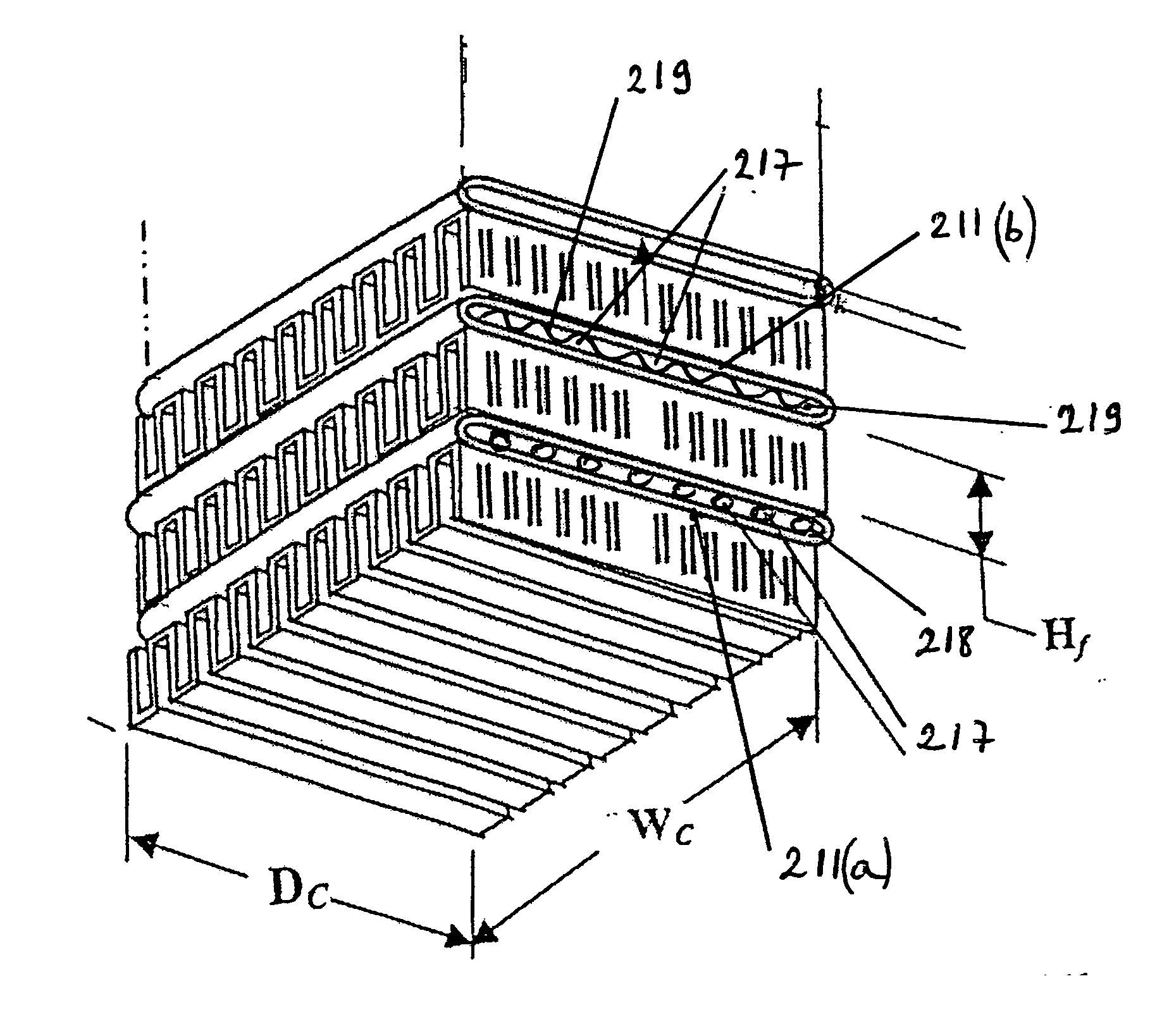
[0022] The present invention describes a heat exchanger wherein one of the preferred embodiments includes an optimized tube height at about 1.5 millimeters, matched with fins at an height of about 6.5 millimeters and establishment of a tube pitch of about 8.0 millimeters for cores with an approximate depth range of about 12 to 44 millimeters. In general, tube optimization may be evaluated in one variable module and fin optimization in a separate module. The fin louvers may vary such that, in preferred aspects of the present invention, the louvers have variable louver angles or widths within an angular range of about 18° to 35°, preferably of about 18° to 28°, with an approximate louver width of about 0.9 millimeters. The fin density range is, preferably, less than or equal to 25 fins per inch.

[0023] In its preferred embodiments, the present invention provides for heat exchangers, and, in particular, engine cooling heat exchangers, with an optimized heat transfer for such exchangers...


PUM


Abstract

The present invention relates to an aluminum heat exchanger. More particularly, the present invention relates to an aluminum heat exchanger useful for motorized power systems similar to those utilized in the automotive industry for engine heat exchange, including, in particular, radiators. In a preferred method, the flat tubes of the heat exchanger are formed from flat sheet braze material and at least one portion is formed approximately normal to the wide portion (major axis) and parallel to the minor axis of the tube.

Description

FIELD OF THE INVENTION [0001] The present invention relates to an aluminum heat exchanger. More particularly, the present invention relates to an aluminum heat exchanger useful for motorized power systems similar to those utilized in the automotive industry for engine heat exchange. BACKGROUND OF THE INVENTION [0002] For a number of years now, industry has been concerned with designing heat exchangers made of various materials, particularly for combustion engines, for both practical and weight reasons. Such materials have included aluminum-based ones such aluminum, aluminum alloy and all-aluminum, in heat exchangers. However, these heat exchangers often have faced the problems of extreme ‘tube side’ or ‘internal’ or ‘coolant’ side pressure drops and manufacturing difficulties that have not been optimally solved or adequately adjusted for in heat exchanger applications. [0003] Industry has also, more specifically, developed automobile heat exchangers employing such elements as flat t...

Claims


Application Information

Patent Timeline
IPC IPC(8): B60Q1/30B60Q3/06F28D1/053F28F1/12F28F21/08G02B1/02G02B13/14
CPCF28D1/05366F28D2021/0094F28F2215/04F28F21/084F28F1/128B60Q1/302B60Q3/30Y10S362/80
Inventor ELBOURINI, REFKI
Owner VALEO INC
Learn More