
Processor temperature adjustment system and method

a temperature adjustment and graphics processor technology, applied in the field of processor operation, can solve the problems of affecting the accuracy of graphics processors, so as to facilitate the maintenance of processor temperature, facilitate processing speed adjustment, and minimize overheating damage to the processor

Active Publication Date: 2011-02-08
NVIDIA CORP
View PDF234 Cites 75 Cited by
  • Summary
  • Abstract
  • Description
  • Claims
  • Application Information

AI Technical Summary

Benefits of technology

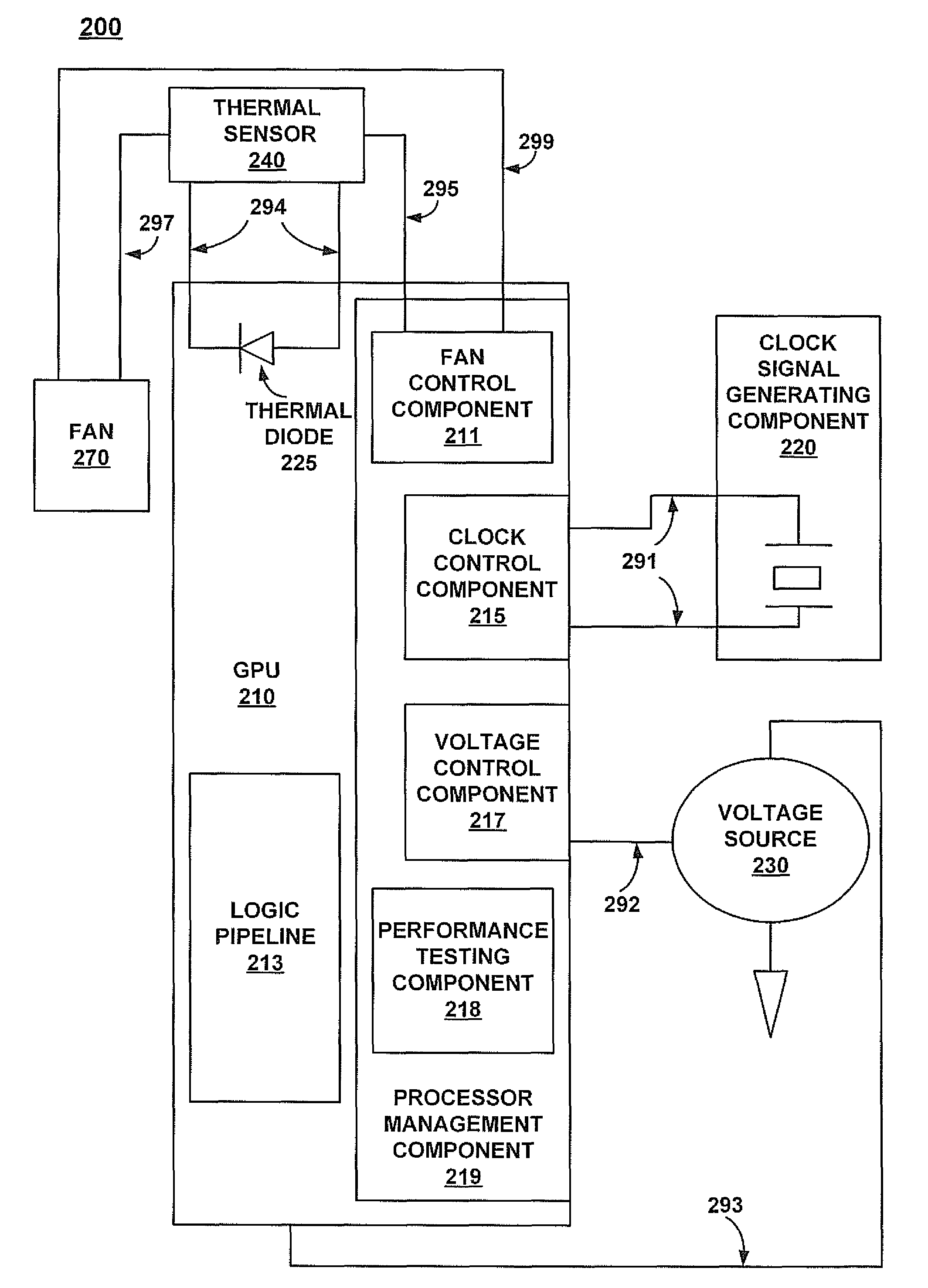
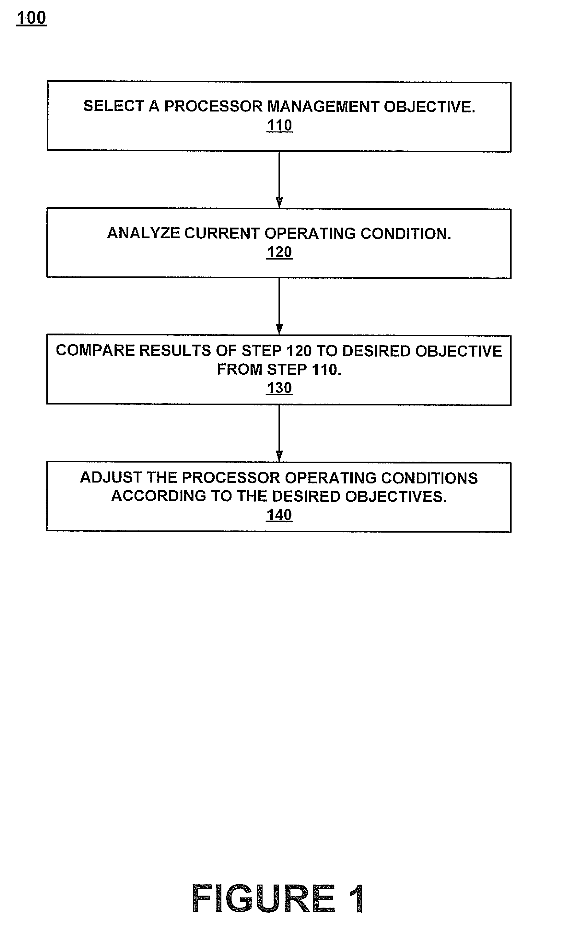
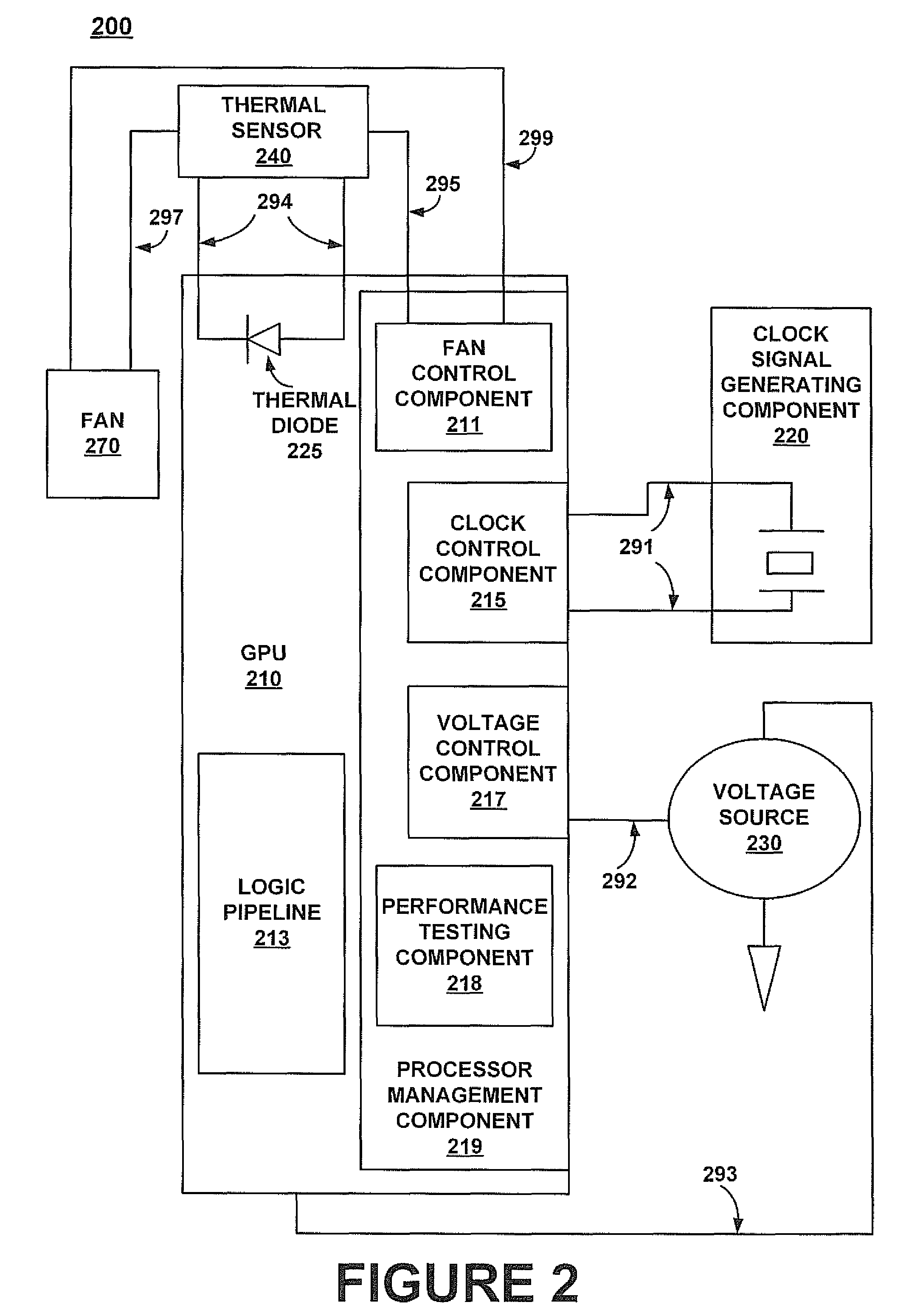
[0009]The present invention facilitates processor speed adjustments within acceptable temperature ranges. In one embodiment, a present invention system includes a temperature sensor that senses the temperature of the processor. When the temperature sensor senses the processor temperature approaching predetermined levels one or more adjustments are performed. For example, the adjustment can include automatically increase or decrease a voltage level in response to crossing a temperature threshold.
[0010]The present invention also facilitates maintenance of a processor temperature within acceptable ranges that minimize overheating damage to the processor. In one embodiment, a present invention temperature maintenance system includes a temperature sensor that senses the temperature of the processor. This sensor can take the form of an on-chip diode and an off-chip voltage-to-temperature measuring device, the device being programmable to set an indicator when any of a plurality of temperature thresholds is crossed. When the temperature sensor senses the processor temperature approaching undesirable levels one or more adjustments are performed. For example, the adjustment can include automatically modulating the frequency of a clock signal associated with the processor. The frequency can be decreased (without software intervention) if the temperature rises beyond a predetermined value or the frequency can be increased to achieve greater performance if the temperature drops below the predetermined value. Voltage can be similarly increased or decreased in response to crossing a temperature threshold. In addition, an interrupt can be generated that causes software to take additional actions to tune the clock frequency in response to temperature measurements.
[0011]Adjustments to the fan operations can also be made to increase cooling when required (e.g., temperature increases beyond predetermined values) or to run in a quiet mode when cooling is not required. In one embodiment, a processor can be configured to run in at least two modes, a quiet mode and a performance mode. In the quiet mode performance is reduced to minimize fan operation as much as possible. In performance mode the fan is directed to operate in a manner that facilitates achievement of maximum performance. In one exemplary implementation, a driver can automatically select between the modes depending on the type of application programs that are running. Alternatively, a user can select the mode via a control panel.
[0012]In one embodiment the present invention provides temperature control via pulse width modulation of the clock signal. For example, a clock speed adjustment circuit picks a variable amount of clock pulses out of 256 clock pulses and removes the rest. This allows an almost continuously variable clock rate, and allows smooth transitions between clock frequencies.

Problems solved by technology

Frequently, these activities involve significant information processing.
However, the speed at which a processor can reliably provide accurate results is limited and typically degrades over time.
Most systems limit processor operation within conservative boundaries and sacrifice possible increased performance so that the processor can meet reliability standards.
However, many graphics presentations, especially interactive 3D graphics presentations, usually require significant processing of large amounts of data at a rapid rate.
Providing image information for each pixel is very data intensive and consumes a significant amount of processing resources.
However, at some point increasing the number of transistors becomes cost prohibitive.
However, increasing the clock frequency is often limited by the characteristics of the transistors utilized to perform the processing.
Higher voltages can be used to sustain operations at a higher clock frequency, and higher clock frequencies and voltage supplies cause a processor to consume more power, thereby increasing the temperature of the processor.
However, higher temperatures generally cause transistors to operate more slowly, causing a lower operational transistor speed.
Continually running a processor at a high temperature stresses the semiconductor device and reduces long term reliability of the device.
There are a number of factors that can affect the degradation of a transistor's ability to quickly and reliably perform switching operations.
The drain current saturation rating of a transistor can be adversely impacted by the temperature and voltage level at which the transistor is operating, causing deterioration in the transistor switching speed.
These limitations impact maximum clock frequencies since transistor reliability is often degraded over time by increased voltage levels and temperatures associated with relatively high clock frequencies.
The fixed nominal frequency is typically not the fastest frequency the processor can possibly operate at and resource utilization is not maximized.
To the extent traditional processing systems attempt clock frequency adjustment, they are usually limited to downward adjustments from the fixed nominal clock frequency to achieve power conservation, further limiting the maximization of processor performance speed.
These attempts are also typically limited in scope (such as a single specific adjustment) and usually have limited or no consideration for impacts on processing performance (e.g., maximized processing speed) or environment (e.g., noise level).
Traditional attempts at processor control typically have limited or no consideration for impacts of frequency, voltage and / or temperature adjustments on maximizing performance while maintaining overall lifetime reliability.
In addition, an interrupt can be generated that causes software to take additional actions to tune the clock frequency in response to temperature measurements.

Method used


Image

  • Processor temperature adjustment system and method
  • Processor temperature adjustment system and method
  • Processor temperature adjustment system and method

Examples


Embodiment Construction

[0031]Reference will now be made in detail to the preferred embodiments of the invention, examples of which are illustrated in the accompanying drawings. While the invention will be described in conjunction with the preferred embodiments, it will be understood that they are not intended to limit the invention to these embodiments. On the contrary, the invention is intended to cover alternatives, modifications and equivalents, which may be included within the spirit and scope of the invention as defined by the appended claims. Furthermore, in the following detailed description of the present invention, numerous specific details are set forth in order to provide a thorough understanding of the present invention. However, it will be obvious to one ordinarily skilled in the art that the present invention may be practiced without these specific details. In other instances, well known methods, procedures, components, and circuits have not been described in detail as not to unnecessarily o...


PUM


Abstract

The present invention facilitates processor speed adjustments within acceptable temperature ranges. In one embodiment, a present invention system includes a temperature sensor that senses the temperature of the processor. When the temperature sensor senses the processor temperature approaching predetermined levels one or more adjustments are performed. For example, the adjustment can include automatically increasing or decreasing a voltage level in response to crossing a temperature threshold.

Description

RELATED APPLICATIONS[0001]This application is a Continuation in part and claims the benefit of and priority to co-pending U.S. patent application Ser. No. 10 / 295,748 filed Nov. 14, 2002; entitled “A PROCESSOR TEMPERATURE AND MODE ADJUSTMENT SYSTEM AND METHOD” and U.S. patent application Ser. No. 10 / 295,619, filed Nov. 14, 2002; entitled “A PROCESSOR PERFORMANCE ADJUSTMENT SYSTEM AND METHOD”, which are both incorporated herein by this reference. The present Application is also related to the following co-pending Application entitled “A Processor Voltage Adjustment System and Method”, application Ser. No. 10 / 448,891 filed May 30, 2003.FIELD OF THE INVENTION[0002]The present invention relates to the field of processor operation. More particularly, the present invention relates to a system and method for adjusting graphics processor performance.BACKGROUND OF THE INVENTION[0003]Electronic systems and circuits have made a significant contribution towards the advancement of modern society ...

Claims


Application Information

Patent Timeline
Patent Type & Authority Patents(United States)
IPC IPC(8): G06F1/00G06F1/26G06F1/32
CPCG06F1/3203G06F1/324G06F1/3296G06F11/24Y02B60/1217Y02B60/1285Y02D10/00
Inventor ALBEN, JONAH M.KRANZUSCH, KEVIN
Owner NVIDIA CORP
Learn More