Multiple-mode fluid valve

a fluid valve and multi-mode technology, applied in the field of multi-mode fluid valves, can solve the problems of difficult to tell exactly what position the valve is, difficult to precisely position the valve, and the “reserve” fuel might already be largely depleted, and achieve the effect of quick and positive rotation

Active Publication Date: 2006-02-23
ILAN GOLAN
View PDF16 Cites 19 Cited by
  • Summary
  • Abstract
  • Description
  • Claims
  • Application Information

AI Technical Summary

Benefits of technology

[0008] It is an object of the present invention to provide a multi-position fuel line valve that may be quickly and positively rotated between full on and off positions, and a position for using the reserve fuel supply.

Problems solved by technology

The device described therein has certain disadvantages, however, in that the polymeric material from which the piston is made is subject to wear over time caused by small particles found in the fuel.
Additionally, without establishing close visual contact with the valve it is sometimes difficult to tell exactly what position the valve is in.
Otherwise, when the user switched between lower portions of the tank the “reserve” fuel might already be largely depleted.

Method used


Image

  • Multiple-mode fluid valve
  • Multiple-mode fluid valve
  • Multiple-mode fluid valve

Examples


first embodiment

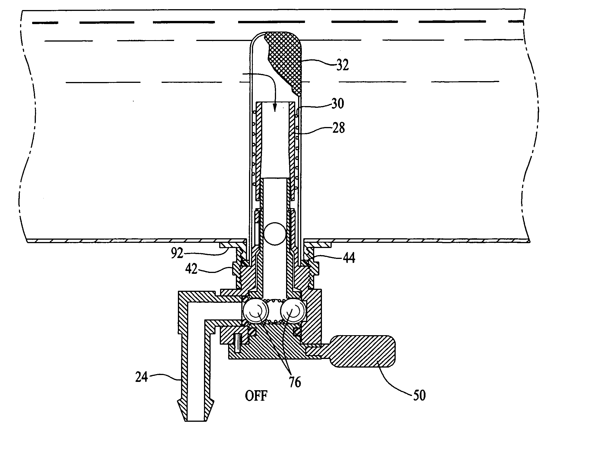
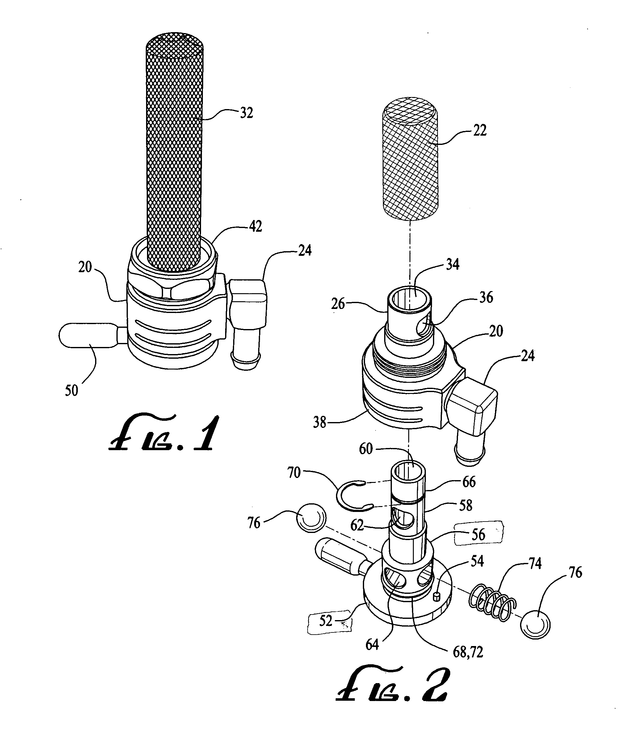
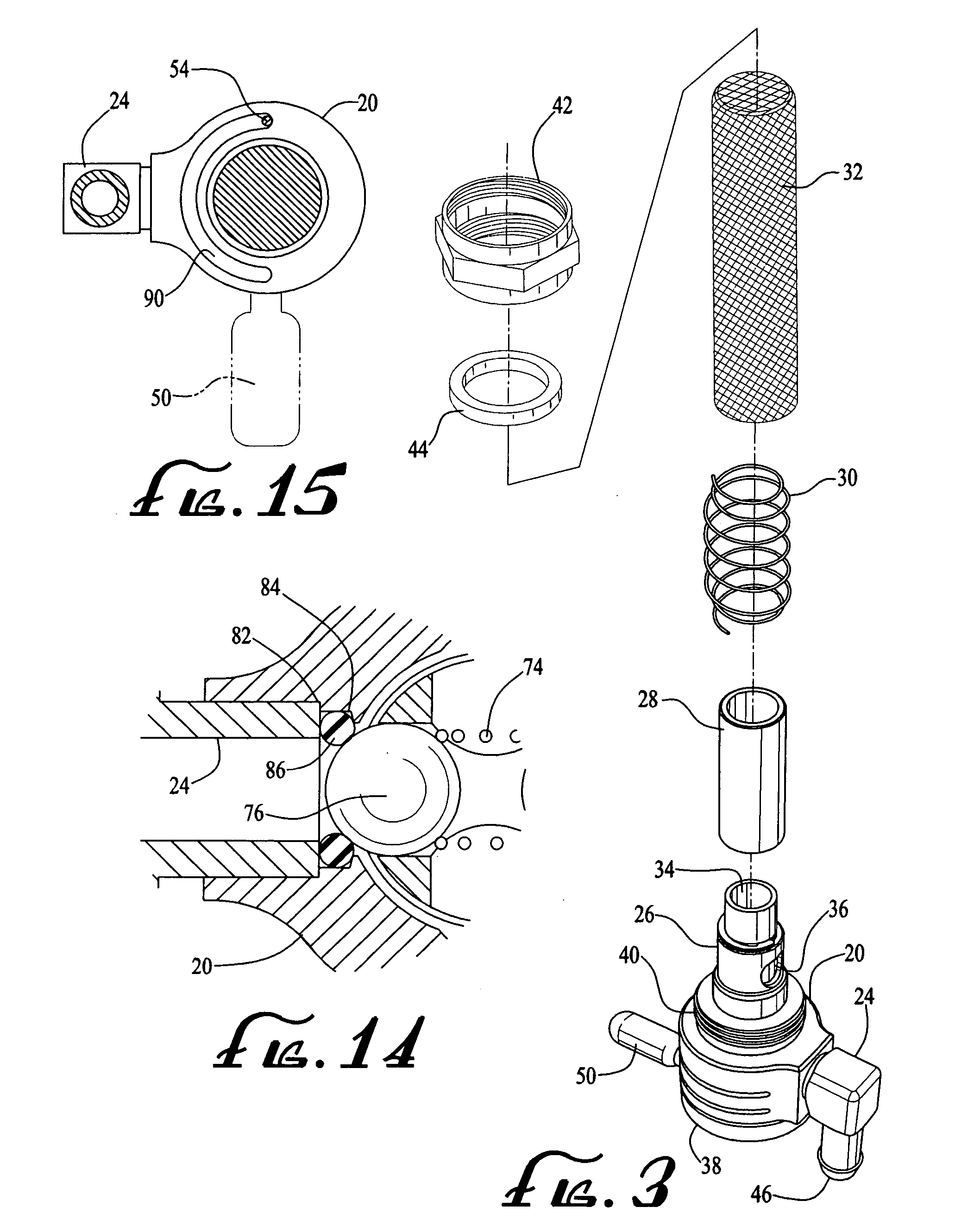
[0221] Now also referring to FIG. 37, the inner workings of the valve can be described. The rotor 324 is in the approximate shape of a bowling pin and revolves inside the chamber 312 of the main body 310. Inside the rotor 324 is a passageway 390 including a pair of intersecting horizontal through holes in the lower portion 328, a vertical hole through the bottom extending upwards past the intersecting through holes to a horizontal exit hole in the upper portion 326 of the rotor. A pair of balls 392 separated by a compression spring 394 and mounted in the lower portion 328 through hole that aligns with the through hole in the upper portion 326. A curved vertical slot 396 is machined into the interior circumferential grove at three places. Where the outlet section 316 meets the main body 310 a space is created to retain an o-ring 398. See FIG. 14 for an enlarged view of this same valve seat structure found in the

fourth embodiment

[0222] The fourth embodiment operates as follows. The valve is mounted to a flat surface remote from the fuel supply and carburetor (all not shown), and fuel hoses (not shown) are connected to the valve. The inlet sections 314, 315 freely swivel (FIGS. 33-35) offering flexibility in routing of the fuel lines. When the selector handle 320 is in the “off” or middle position the balls 392 are seated against the o-ring 394 and in the vertical slot 396 180 degrees opposite, and the outlet section 316 is sealed and no fuel is able to pass through the valve. Also while in the “off” position, the rotor 324 is oriented such that the hole in the upper portion 326 of the passageway 390 is misaligned with the inlet sections 314, 315 such that no significant amount of fuel is able to pass into the valve from either of the inlet sections 314, 315.

[0223] When the selector handle 320 is rotated 90 degrees counter-clockwise (looking down at the top of the valve), the rotor 324 revolves 90 degrees in...


PUM


Abstract

A multi-position fuel valve includes a main body having an enclosed chamber with a number of inlet ports and an outlet port and associated seats in the chamber. Disposed inside the chamber is a revolving rotor that is connected to a selector handle located outside the chamber. The rotor provides a possible passageway between each of the inlet ports and the outlet port. The handle can rotate a maximum 180 degrees, and the valve has a pair of inlet sections and three-positions with an “off” position approximately midway between the other two positions. A pair of balls are positioned in the rotor and lodge in the plurality of seats or elsewhere in the chamber. When this occurs a certain portion of the passageway is cut off meaning there is no fluid flow from at least one of inlet ports through the outlet port. A compression spring with opposing ends bearing against the balls maintains the balls lodged in the seats, and releasably fixes the position of the rotor and handle. The valve further has a number of swiveling extension sections connected to the ports for inlet or outlet hoses, such that the valve can be mounted remote from the fuel supply and/or carburetor and connecting hosed routed in most any direction.

Description

CROSS-REFERENCE TO RELATED DOCUMENTS [0001] This application is based in part on provisional application Ser. No. 60 / 585,190 filed Jul. 1, 2004 entitled “Motorcycle Fuel System Petcock Valve,” and provisional application Ser. No. 60 / 602,426 filed Aug. 17, 2004 and 60 / 662,153 filed Mar. 15, 2005, both entitled “Remote Fuel Supply Valve For Motorcycles,” all of which are incorporated by reference herein.BACKGROUND OF THE INVENTION [0002] 1. Field of the Invention [0003] This present invention is directed to a multi-position fuel line valve particularly adapted for use on a motorcycle including a “chopper.”[0004] 2. Description of the Related Art [0005] Petcock or selector valves provide a motorcyclist with the ability to switch from an “on” or running position to a “reserve” position (i.e. allowing in fuel from the bottom of the tank (or possibly from a separate tank), typically while the motorcycle is traveling), as well as a fuel line shut “off” position. The Golan U.S. Pat. No. 6,1...

Claims


Application Information

Patent Timeline
Patent Type & Authority Applications(United States)
IPC IPC(8): F16K11/08
CPCF02M37/0023F16K15/183F16K11/0856F02M37/0082F16K15/1823Y10T137/86348Y10T137/86823Y10T137/86863Y10T137/88038
Inventor GOLAN, IIAN Z.COHEN, DANIEL
Owner ILAN GOLAN
Why Eureka
Try Eureka