Hand tool having an adjustable head with a joint lock mechanism

a technology of adjustable head and joint lock mechanism, which is applied in the direction of wrenches, screwdrivers, manufacturing tools, etc., can solve the problems of reducing the life of wrenches, unable to effectively lock the head, and the wrench cannot sustain high torque, so as to achieve a more secure positioning and easy operation

Active Publication Date: 2006-03-02
DANAHER TOOL
View PDF14 Cites 13 Cited by
  • Summary
  • Abstract
  • Description
  • Claims
  • Application Information

AI Technical Summary

Benefits of technology

[0007] It is an object of the present invention to provide a hand tool having an adjustable head with a joint lock mechanism, easier and more secured positioning.

Problems solved by technology

However, this kind of wrench cannot sustain high torque due to the configuration of the slots in the extended portion of the push button and the extended portion of the pin.
In addition, since the extended portion of the pin is slidable with respect to the slot of the push button, it is not possible to lock the head effectively.
Moreover, the extended portion of the push button and the extended portion of the pin may be worn out or fractured after use for a long period, which subsequently causes inconvenience when they are in use and reduces the life time of the wrench.
Again, this kind of wrench cannot sustain high torque.
In addition, since the teethed portion of the convex portion is of a sharp arc shape, it is likely that the teethed portion may be fractured due to high torque which renders the wrench un-useable.

Method used


Image

  • Hand tool having an adjustable head with a joint lock mechanism
  • Hand tool having an adjustable head with a joint lock mechanism
  • Hand tool having an adjustable head with a joint lock mechanism

Examples


Embodiment Construction

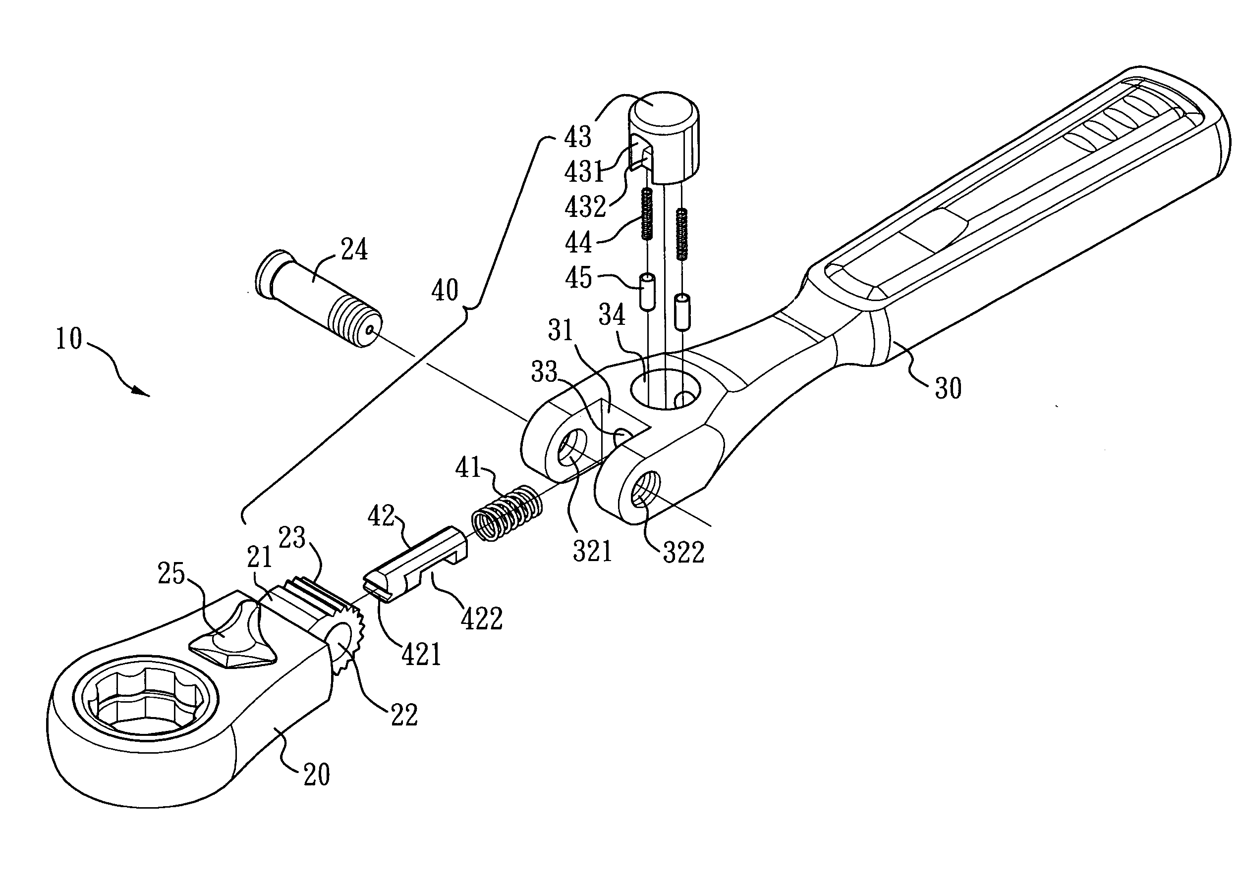
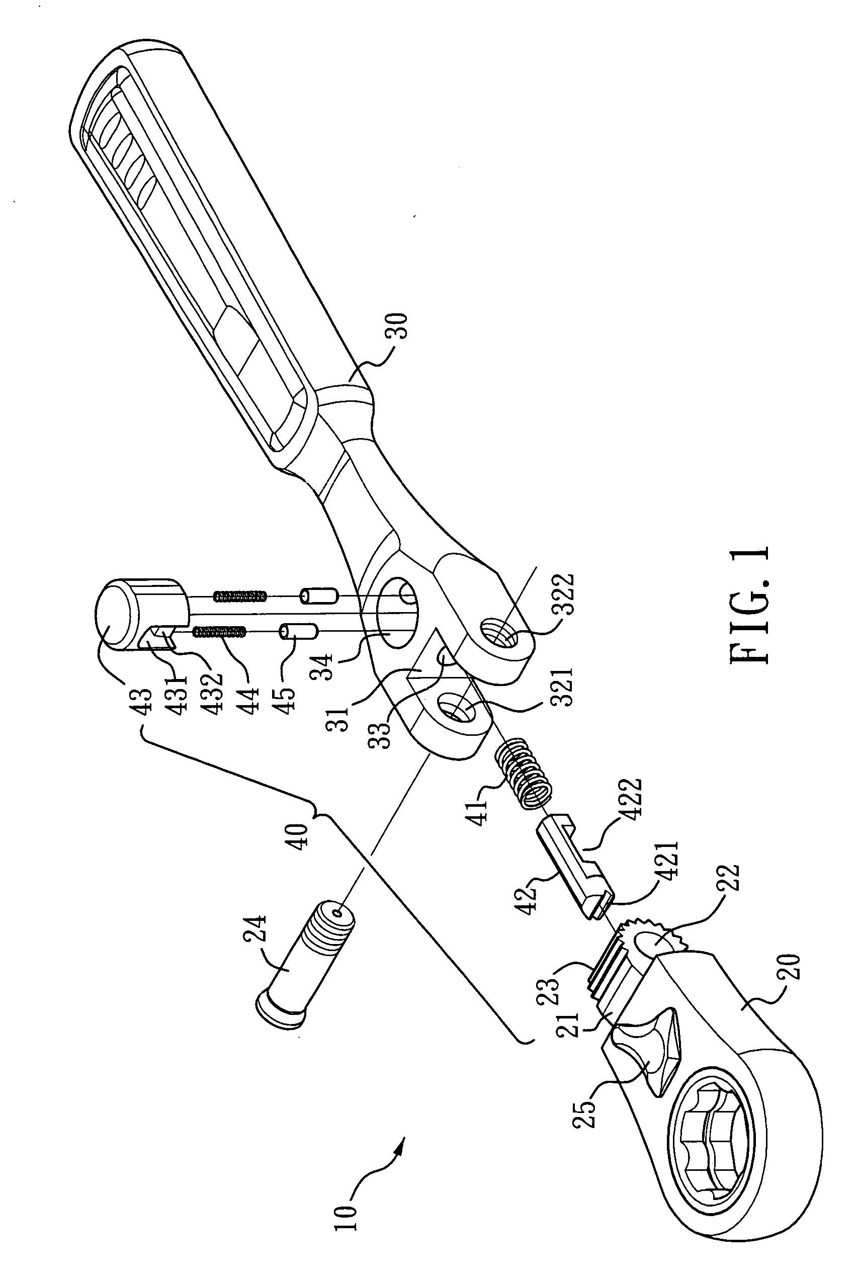
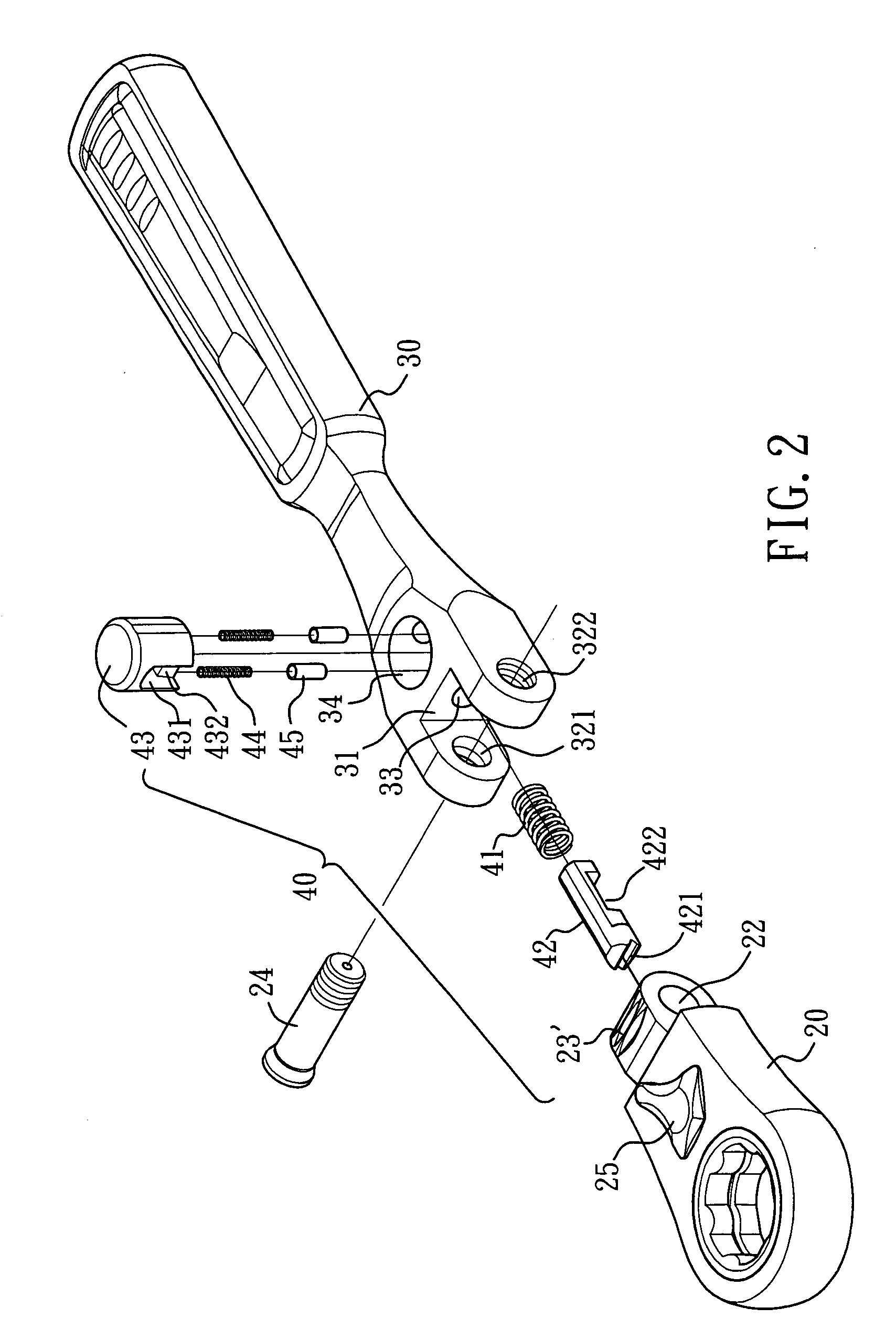
[0026]FIGS. 1 and 2 illustrate an exploded view of a handle tool having an adjustable head with a joint lock mechanism according to the present invention. A wrench 10 comprises a head 20, a handle 30 and a joint lock mechanism 40. A convex portion 21 is formed at a rear end of the head 20 and a through hole 22 is formed through the convex portion 21. A concave portion 31 is formed at a front end of the handle 30. A through hole 321 and a threaded hole 322 are formed at opposite sides thereof to receive a screw 24 or other suitable fastening device for pivotally coupling the head 20 to the handle 30 such that the head 20 is pivotally coupled with respect to the screw 24 while the handle is fixedly coupled with respect to the screw 24. Regarding the configuration between the screw 24, the through hole 321 and the threaded hole 322, please refer to TW566274 for more details. A first aperture 33 is formed at the front end of the handle 30 and substantially extends along the length there...


PUM


Abstract

A hand tool having an adjustable head with a joint lock mechanism comprises a head having a rear end and a handle having a front end pivotally coupled to the rear end of the head. The handle has a first aperture longitudinally extending at the front end thereof and a second aperture is formed perpendicularly intersecting the first aperture. The joint lock mechanism is disposed between the rear end of the head and the front end of the handle and further comprises: a first engaging device disposed at the rear end of the head; a second engaging device received in the first aperture, the second engaging device having a front end and a rear end; a pull button received in the second aperture; and a first elastic device received in the first aperture such that the second engaging device is provided with a forward force to engage the front end of the second engaging device with the first engaging device; characterised in that: the push button is formed with a through hole and provided with a first engaging portion being disposed beneath the through hole; the second engaging device passes through the push button and abuts against the first elastic device; the second engaging device is disposed with a second engaging portion and a second elastic device is disposed at the bottom of the push button such that the push button is provided with an upward force to engage the first engaging portion with the second engaging portion.

Description

BACKGROUND OF THE INVENTION [0001] 1. Field of the Invention [0002] The present invention relates to a hand tool having an adjustable head with a joint lock mechanism, especially a hand tool with a head of adjustable angles and easier, more secured positioning. The present application claims priority based on ROC (Taiwan) Patent Application No. 093213843. [0003] 2. Description of the Related Art [0004] Conventional hand tools with an adjustable head, such as those disclosed in U.S. Pat. No. 6,216,567, comprise a head and a handle. The head has a convex portion which can be pivotally coupled to a concave portion of the handle by a screw. A joint lock mechanism comprises a teethed portion formed along the surface of the convex portion, a pin and a push button. The pin is received in a longitudinal hole having a shoulder portion and extending along the length of the handle. A teethed portion is formed at one end of the pin opposite to, the teethed portion of the convex portion while th...

Claims


Application Information

Patent Timeline
Patent Type & Authority Applications(United States)
IPC IPC(8): B25B23/16B25G1/00B25B23/00B25G1/06
CPCB25G1/063
Inventor LIN, YU-CHENG
Owner DANAHER TOOL
Why Eureka
Try Eureka