Energy reclaiming process

a technology of energy reclaiming and process, applied in the field of gaseous sources, can solve the problem of low thermal efficiency

Inactive Publication Date: 2006-03-09
HELLEUR DONALD
View PDF6 Cites 42 Cited by
  • Summary
  • Abstract
  • Description
  • Claims
  • Application Information

AI Technical Summary

Problems solved by technology

Present processes release large volumes of gas into the atmosphere, resulting in a loss of energy, especially the latent heat of any condensable vapor, resulting in low thermal efficiencies.

Method used


Image

  • Energy reclaiming process
  • Energy reclaiming process
  • Energy reclaiming process

Examples


examples

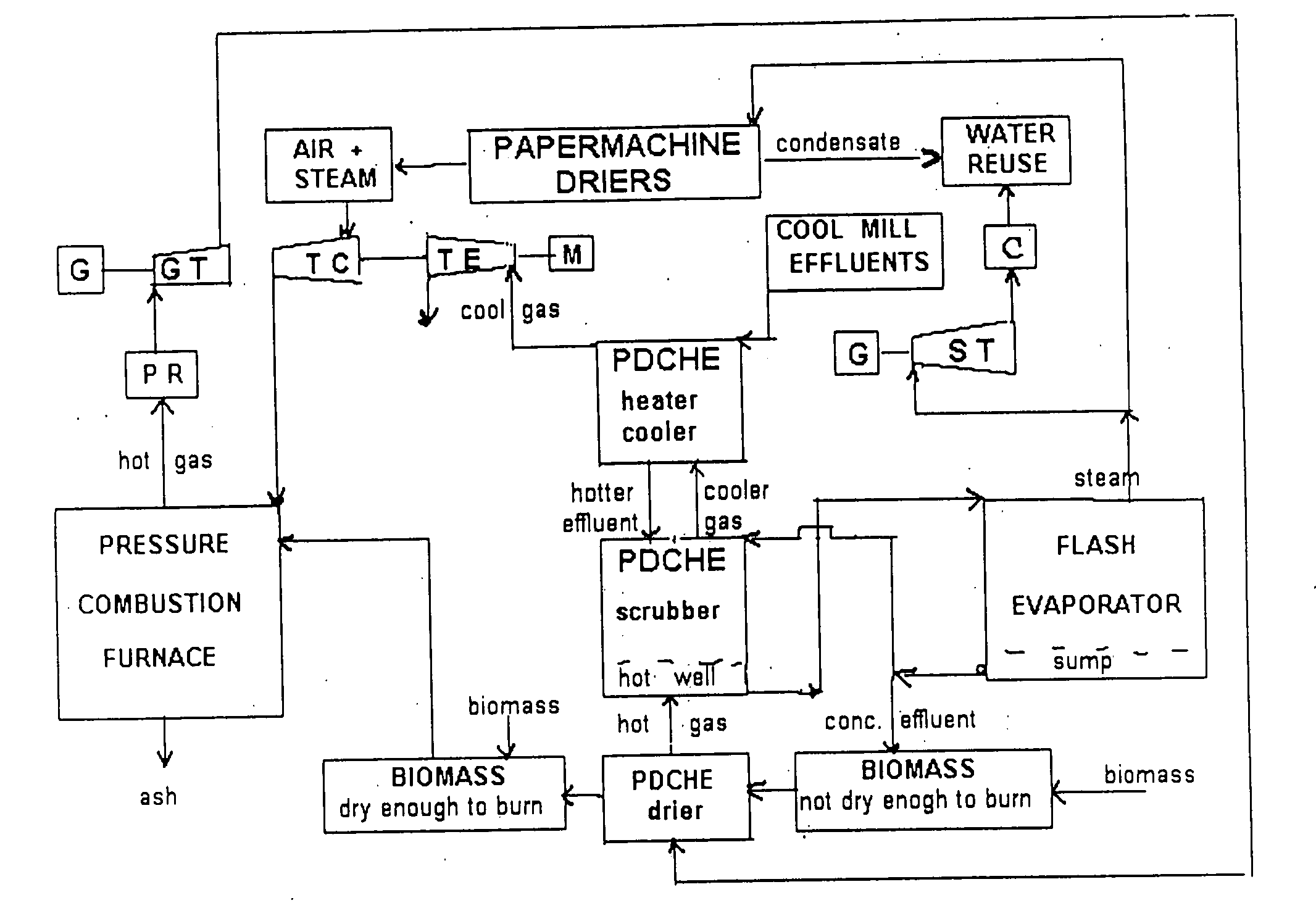
[0058] Combustion / incineration of materials that produce water vapor, e.g. wet combustibles. While some emphasis is on biomass fuels, the process could have application to the combustion of (a) solid / liquid fossils fuels; (b) fuels intermediate between the two i.e. lignite (brown coal), peat, etc, where the high moisture content is a deterrent to their use; (c) Diverse fuels, such as Tire Derived Fuel (TDF), and various sludges, etc. (2) Diverse processes such the smelting of ores; wet oxidation; chemical, electrochemical, metallurgical processes (blast furnaces), and intermediary operations such as: drying; stripping, extraction; boiling and the like.

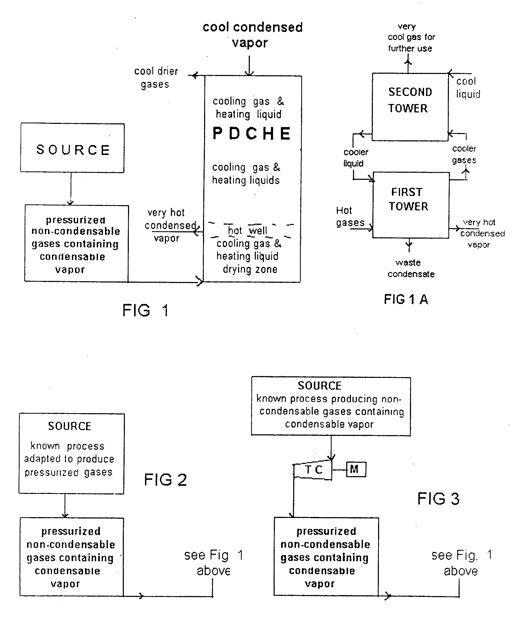
[0059] In FIG. 3, there is shown an arrangement wherein the increase in pressure of the source process cannot be carried out, then the gases from the source process are turbo-compressed to the desired pressure, with the temperature increased by the compression. For example in the drying of pulp or paper, enormous quantities of air and...


PUM


Abstract

The invention relates to gaseous sources from which to reclaim energy using a pressurized direct contact heat exchanger, and in particular, those sources containing a condensable vapor. While the main applications involve water as the condensable vapor, the process is applicable to other vapors, e.g. those in the chemical and petroleum industries where various organic solvents are used. The reclaimed energy can be in the form of a hot fluid, process steam and or electricity. It has particular application to: a pressure combustion furnace and the DOE's Clean Coal Technology; the combustion of wet fuels (biomass, peat); pulp & paper; electrolysis of alumina or water; detoxidation, thermal depolymerization, enhanced oil recovery (and sequestering of carbon dioxide), phytotechnology,

Description

[0001] The present application is a continuation-in-part of application Ser. No. 10 / 780,199 filed Jul. 9, 2004.FIELD OF THE INVENTION [0002] The invention relates to gaseous sources from which to reclaim energy using a pressurized direct contact heat exchanger. In particular, those sources containing a condensable vapor While the main applications involve water as the condensable vapor, the process is applicable to other vapors, e.g. those in the chemical and petroleum industries where various organic solvents are used. [0003] The reclaimed energy-can be in the form of a hot fluid, process steam and / or electricity. It has particular application to: a pressure combustion furnace and to DOE's Clean Coal Technology; the combustion of wet fuels (biomass, peat); pulp &paper; electrolysis of alumina or water; wet oxidation, thermal depolymerization, enhanced oil recovery (and sequestering of carbon dioxide), phytotechnology, [0004] If the source is not already under pressure, the inventio...

Claims


Application Information

Patent Timeline
Patent Type & Authority Applications(United States)
IPC IPC(8): F28F13/06F01K3/18
CPCF01K3/185
Inventor HELLEUR, DONALD
Owner HELLEUR DONALD
Why Eureka
Try Eureka