

Repair method for noise suppression structure
- Summary
- Abstract
- Description
- Claims
- Application Information
AI Technical Summary
Problems solved by technology
Method used
Image

Examples
Embodiment Construction
[0023] Before proceeding with the detailed description, it is to be appreciated that the described embodiment is not limited to use in conjunction with a particular type of engine, or in a particular type of vehicle. Thus, although the present embodiment is, for convenience of explanation, described as being implemented in an aircraft environment, it will be appreciated that it can be implemented in various other types of vehicles, and in various other systems and environments.
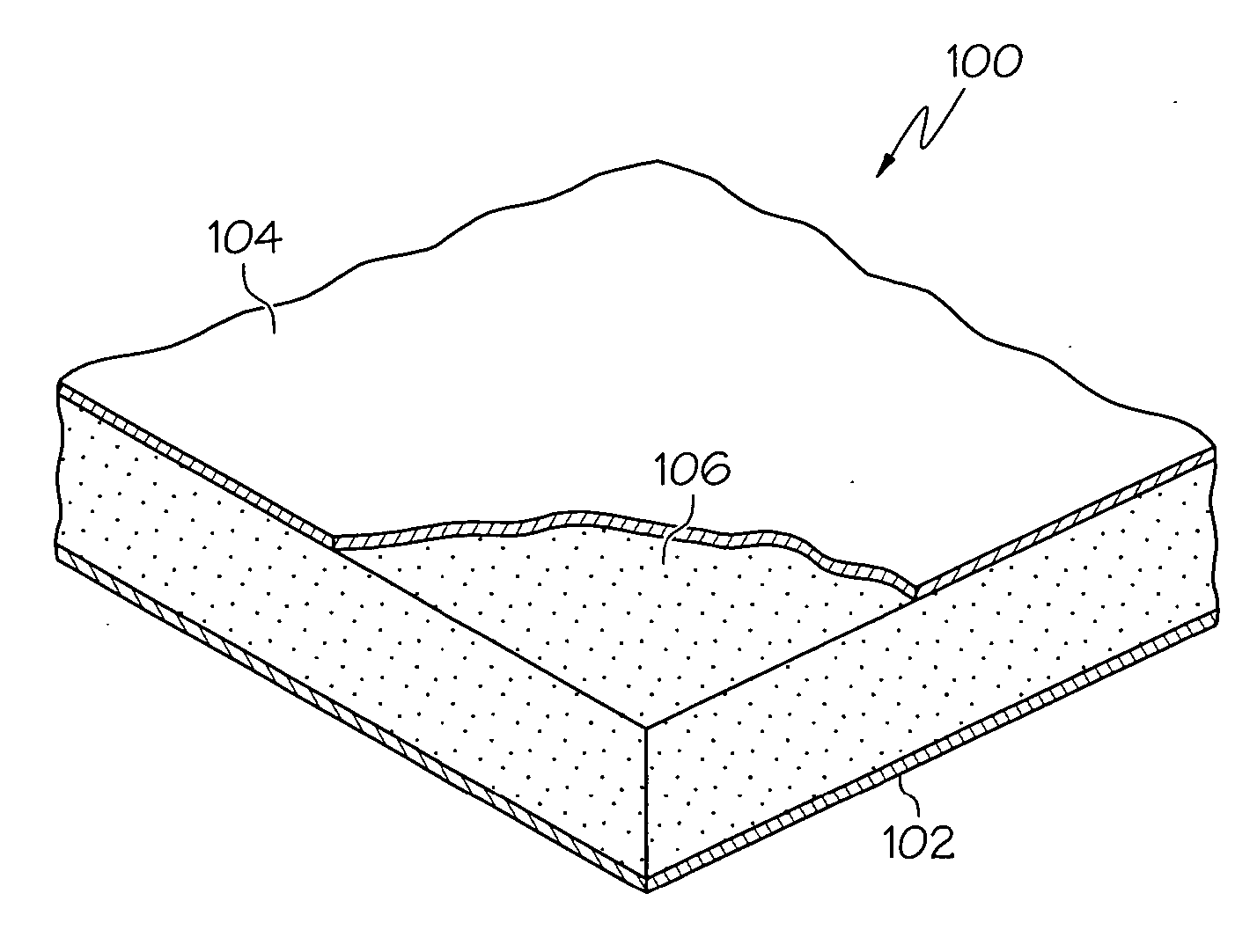
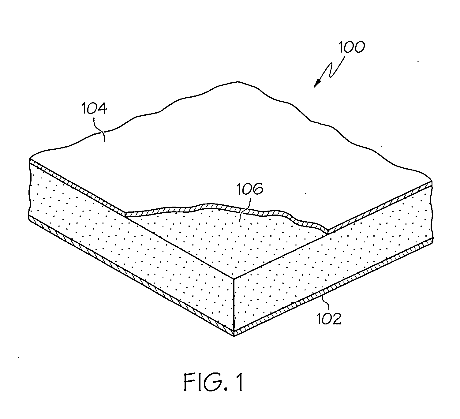
[0024] Turning now to the description, and with reference first to FIG. 1, an exemplary noise suppression panel 100 is depicted in perspective and cross section, respectively. In FIG. 1, the panel 100 includes a back plate 102, a face plate 104, and a bulk absorber 106. The back plate 102 is preferably imperforate and is constructed of any one of numerous types of non-porous materials such as, for example, aluminum, epoxy, or bismaleimide (BMI). As will be described more fully below, the back plate 102 is pre...
PUM
| Property | Measurement | Unit |
|---|---|---|
| Fraction | aaaaa | aaaaa |
| Temperature | aaaaa | aaaaa |
| Area | aaaaa | aaaaa |
Abstract
Description
Claims
Application Information