
Horizontal rotary hook for sewing machine

Active Publication Date: 2006-03-30
BROTHER KOGYO KK
View PDF6 Cites 4 Cited by
  • Summary
  • Abstract
  • Description
  • Claims
  • Application Information

AI Technical Summary

Benefits of technology

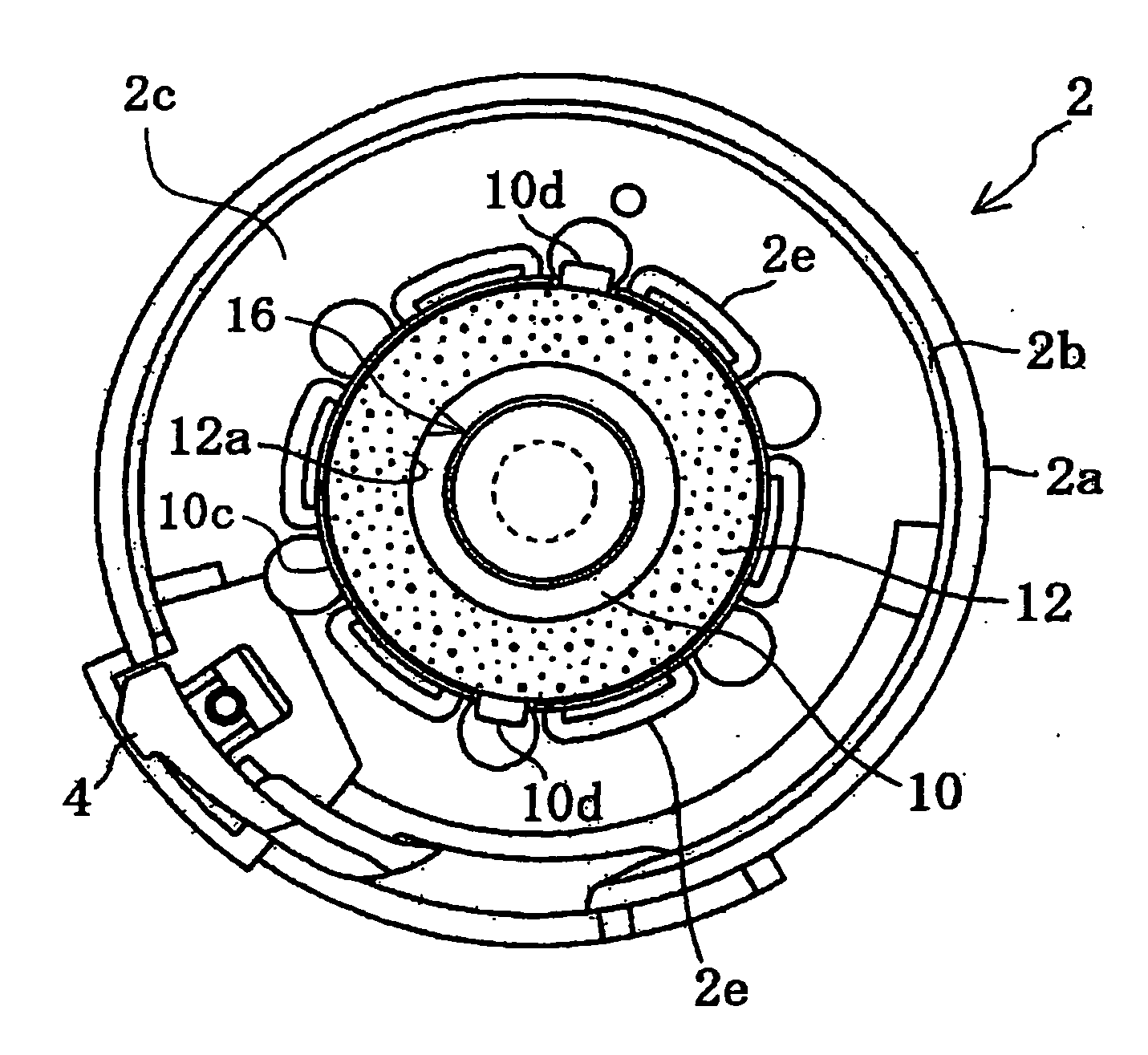
[0008] The purpose of the present invention is to provide a horizontal rotary hook of a sewing machine capable of obtaining sufficient attraction between an inner rotary hook and an outer rotary hook while restraining the size increase of the entire construction.
[0010] The yoke member is integrally formed with a bottom wall contacting the magnet piece and a surrounding wall surrounding the outer circumference of the magnet piece. In the present invention, the floating of the inner rotary hook from the outer rotary hook is prevented by pulling the inner rotary hook toward the outer rotary hook by a magnetic attraction between the adsorption plate made of and the thin plate-shaped magnet piece. At this point, since the magnet piece is provided in a housed state in the yoke member integrally formed with a bottom wall and a surrounding wall, a magnetic path is formed extending from the top surface of the magnet piece to the bottom surface of the magnet piece via the adsorption plate, the surrounding wall, the bottom wall of the yoke member and the bottom surface of the magnet piece. Hence, even if the magnet piece is relatively small, the magnetic attraction between the magnet piece and the adsorption plate can be increased, thereby increasing the magnetic force to pull the inner rotary hook toward the outer rotary hook.

Problems solved by technology

However, a simple provision of a magnet in the outer rotary hook made of synthetic resin would limit the magnet to a relatively small size, consequently providing insufficient attraction with respect to the inner rotary hook.
As a result, the floating of the inner rotary hook is not prevented effectively.
Such being the case, mounting of a large type magnet generating strong magnetic force on the outer rotary hook is a possible alternative; however, such countermeasures give rise to problems such as cost and size increase of the horizontal rotary hook.
However, this will result in complicated assembly work and furthermore, since the magnet is of small size, consequently having small adhesion area incapable of providing enough adhesion, problems have occurred where the magnet fell off while in use.

Method used


Image

  • Horizontal rotary hook for sewing machine
  • Horizontal rotary hook for sewing machine
  • Horizontal rotary hook for sewing machine

Examples


Embodiment Construction

[0021] An embodiment of the present invention is described hereinafter with reference to the drawings. The present embodiment is an example applying the present invention to a horizontal full rotary hook rotatably driven continuously in one direction.

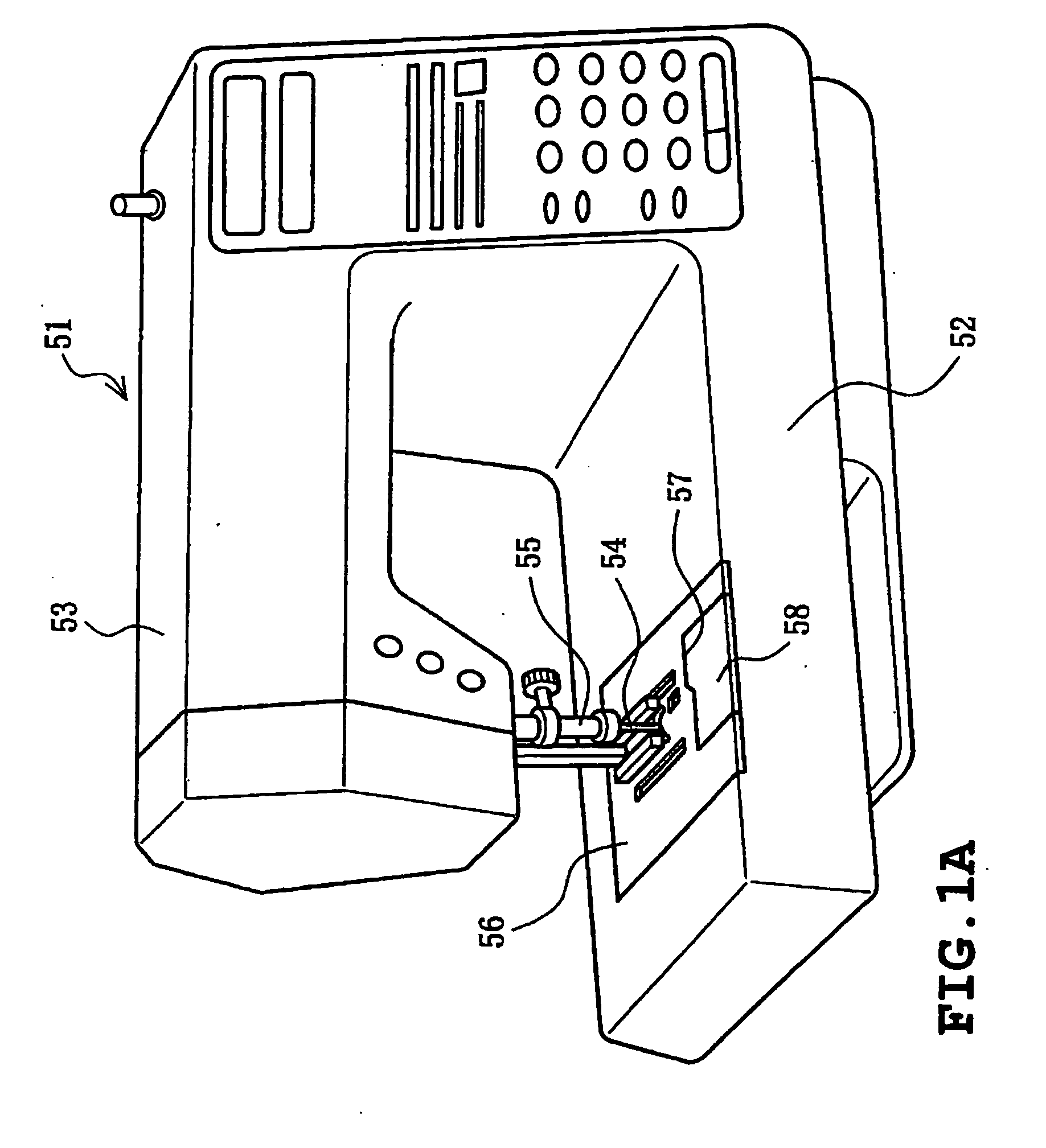
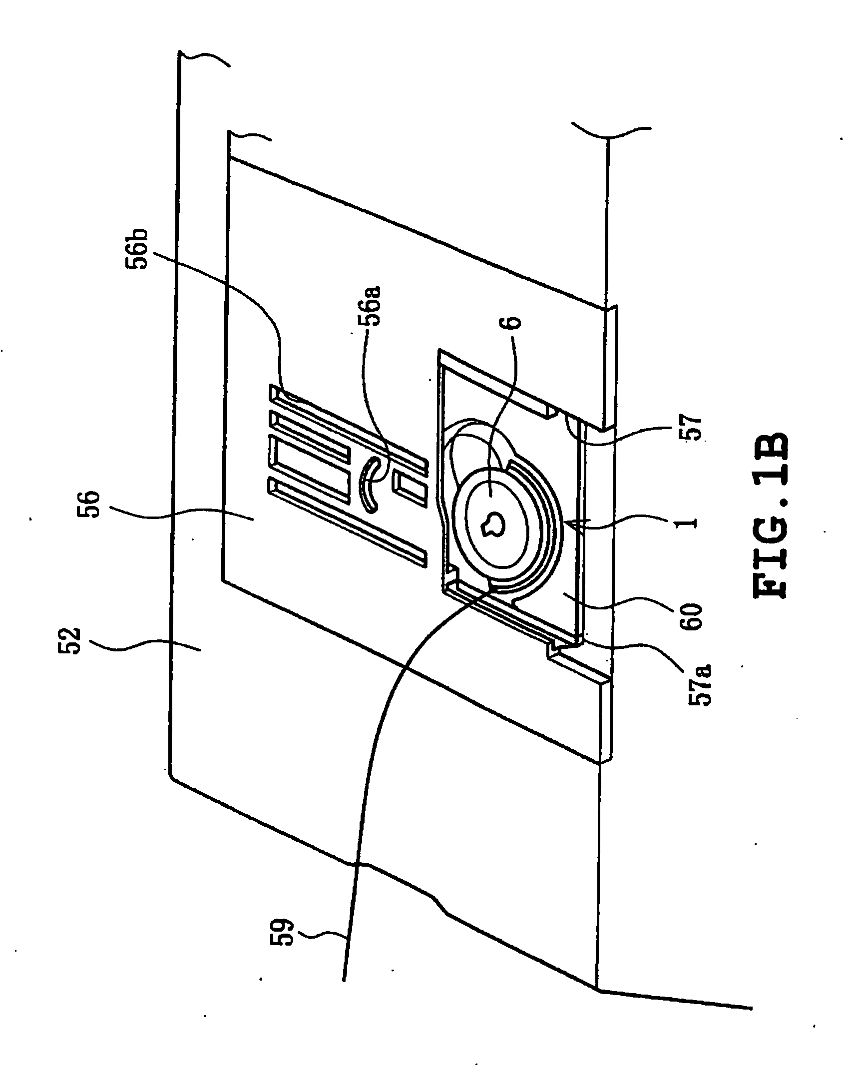
[0022] First, an overall construction of a sewing machine according to the present embodiment is described with reference to FIGS. 1A and 1B.

[0023] The sewing machine body 51 as shown in FIG. 1A is integrally formed with an arm 53 above the bed 52. A needle bar 55 having a sewing needle 54 is provided on a distal end of the arm 53 and is vertically moved by a driving mechanism not shown. On the other hand, as also shown in FIG. 1B, a metal needle plate 56 is provided on the upper surface of the bed 52 opposing the needle bar 55. On the needle plate 56 are formed a needle hole 56a through which the needle bar 55 penetrates and plurality of long holes 56b for operation of a feed dog not shown. Also, a bobbin accommodation hole 57 having...


PUM


Abstract

A horizontal rotary hook of a sewing machine includes an inner rotary hook made of synthetic resin and housing a bobbin, an outer rotary hook made of synthetic resin and housing the inner rotary hook and rotated in a predetermined direction, an adsorption plate made of a magnetic material and mounted on one of an outer surface of a bottom wall of the inner rotary hook and an inner surface of a bottom wall of the outer rotary hook, a magnet piece formed as a thin plate and mounted in the other of the outer surface of the bottom wall of the inner rotary hook and the inner surface of the bottom wall of the outer rotary hook, and a yoke member made of a magnetic material and housing the magnet piece integrally formed with a bottom wall contacting the magnet piece and a wall surrounding an outer circumferential side of the magnet piece. The yoke member is mounted on the other of the outer surface of the bottom wall of the inner rotary hook and the inner surface of the bottom wall of the outer rotary hook.

Description

CROSS-REFERENCE TO RELATED APPLICATIONS [0001] This application is based upon and claims the benefit of priority from the prior Japanese Patent Application No. 2004-281375, filed on Sep. 28, 2004 the entire contents of which are incorporated herein by reference. BACKGROUND OF THE INVENTION [0002] 1. Field of the Invention [0003] The present invention relates to a horizontal rotary hook of a sewing machine provided with an inner rotary hook and an outer rotary hook respectively made of synthetic resin wherein the inner rotary hook is pulled toward the outer rotary hook by the magnetic force of a thin plate-shaped magnet piece. [0004] 2. Description of Prior Art [0005] Conventionally, horizontal rotary hooks offering simple and handy bobbin exchange have been widely used. Such types of horizontal rotary hooks are provided with an outer rotary hook formed with a race surface and an inner rotary hook housing a bobbin retained rotatably in relative to the race surface. The outer rotary h...

Claims


Application Information

Patent Timeline
IPC IPC(8): D05B57/14
CPCD05B57/20D05B57/143
Inventor OTA, SHINNAKASHIMA, AKIFUMIMIZUNO, KENICHI
Owner BROTHER KOGYO KK
Learn More