Grouping mesh clusters

a technology of grouping and clustering, applied in non-electric variable control, process and machine control, instruments, etc., can solve the problems of prohibitive labor involved in running the communication wires, the availability of existing communication, and the cost of extending the communication wires, so as to reduce the number of devices or repeaters, the effect of high transmission bandwidth

Inactive Publication Date: 2006-03-30
POWER MEASUREMENT LTD
View PDF28 Cites 100 Cited by
  • Summary
  • Abstract
  • Description
  • Claims
  • Application Information

AI Technical Summary

Benefits of technology

[0013] Embodiments of the invention relate to systems and methods for grouping mesh clusters. The grouped mesh clusters are used, by way of example, to transmit energy data collected by an energy sensor or other monitoring device to a destination device such as an energy management station.

Problems solved by technology

Typically metering a particular point within an energy distribution system, such as an electrical distribution system, can be very costly and there are monetary and practical barriers to installing metering points.
Some of these costs are external components such as potential transformers or current transformers, commissioning costs, measurement cabinet costs and installation costs.
A large installation cost associated with metering points is the cost and installation of communication wires including conduits for the communication wires.
The availability of existing communication, cost of extending those communications, and the labor involved in running the communication wires can be prohibitive when evaluating the benefit of adding a new metering point.
This approach is prone to human error in addition over time it can be an expensive communication method.
Another large installation cost associated with some metering points is the cost of providing an adequate power supply or separate power supply to the metering device.
There may not be a conventional power supply for the metering device accessible; in which case, additional installation expense is required to provide control power to the metering device.
A further installation cost associated with the physical mounting to the metering point.
Many times display holes and screw holes must be made in the measurement cabinet or a measurement cabinet itself must be purchased further adding to the installation costs.
Typically, commissioni

Method used


Image

  • Grouping mesh clusters
  • Grouping mesh clusters
  • Grouping mesh clusters

Examples


Embodiment Construction

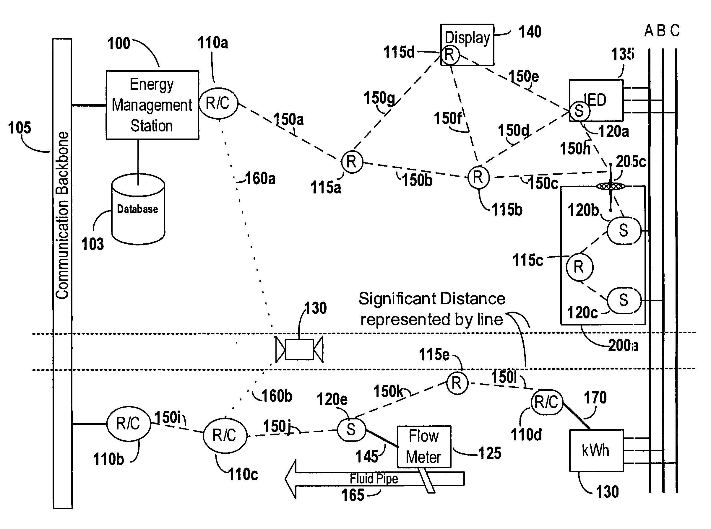
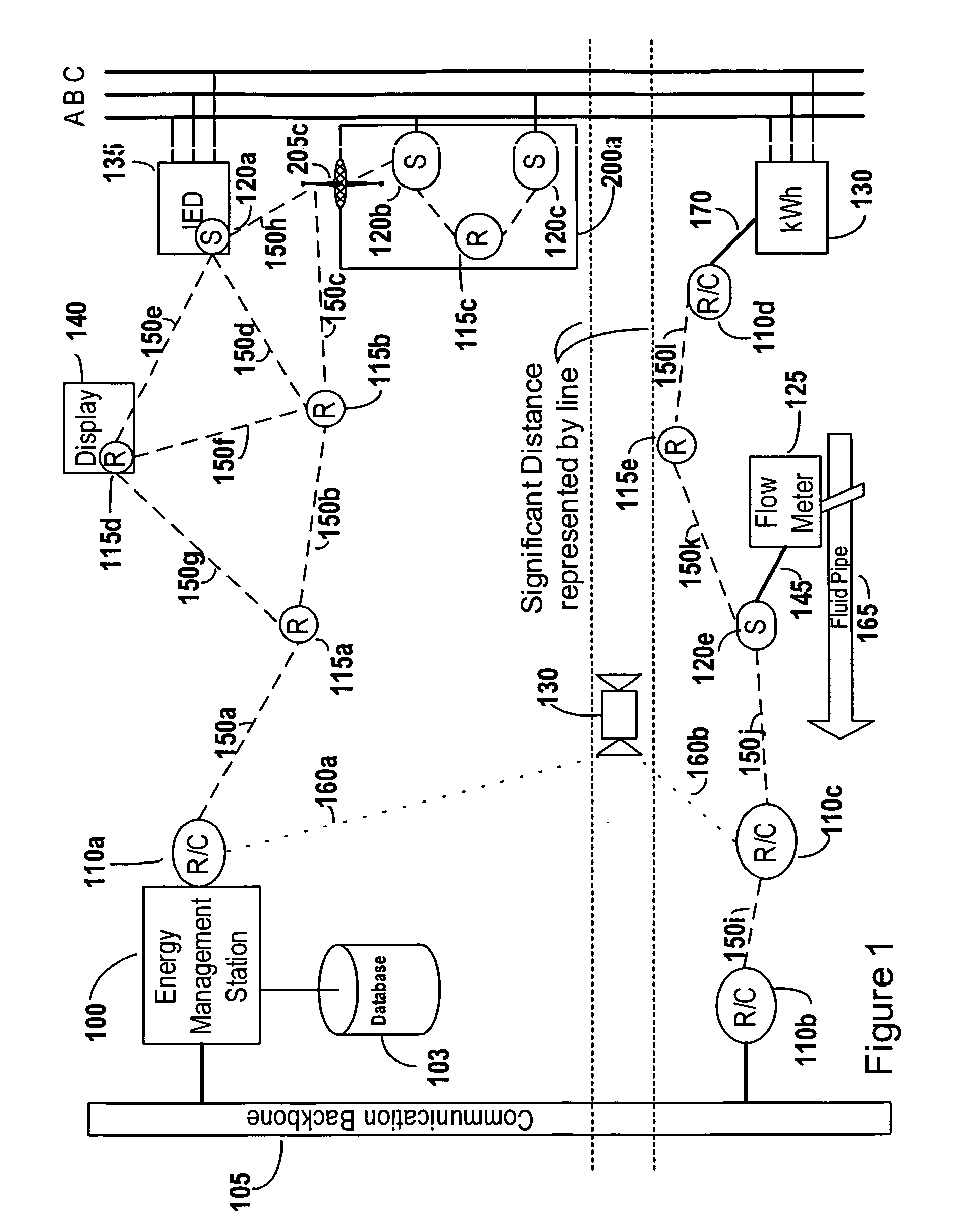
[0027] Herein, the phrase “coupled with” is defined to mean directly connected to or indirectly connected through one or more intermediate components. Such intermediate components may include hardware, communication and software-based components. Additional intermediate components may include electrical field coupled and magnetic field coupled components. The figures included in this document refer to various groups of items using a number prefix and a letter as a suffix, such as 110a, 110b, and 110c. The number listed alone without the letter suffix refers to at least one of these items. An example of this is when a group of items such as the repeater converters are referred to as repeater converters 110, this is meant to refer at least one of the repeater converters 110a, 110b, or 110c.

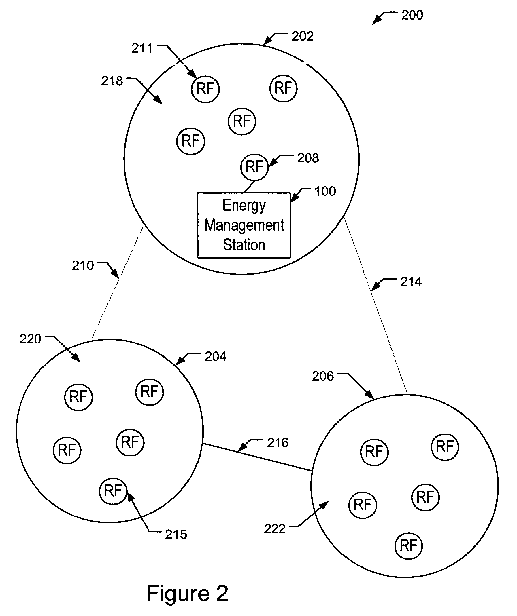
[0028] Embodiments of the invention relate to systems and methods for grouping mesh networks, also referred to herein as mesh clusters. In some instances, grouping mesh networks may include splitti...


PUM


Abstract

Systems and methods for grouping mesh networks. Mesh networks enable energy data to be transferred from an energy sensing device to a destination device using various networks and reduces the need to install metering stations. Embodiments of the invention join or group mesh networks that otherwise are not able to communicate. The connections between the grouped mesh networks can be passive using directional antennas or passive antennas or active using higher power RF devices, solar repeaters, mobile mesh devices, etc. The energy data is routed in a smart manner, by performing load balancing at gateways, by monitoring the signal to noise ratio of available communication paths, etc. Mesh clusters can also be created to define low power clusters, address blocking clusters, and frequency based clusters. Grouping clusters facilitates the efficient transfer of energy data from an energy sensing device to a energy management station.

Description

CROSS-REFERENCE TO RELATED APPLICATIONS [0001] This application is a continuation-in-part of U.S. patent application Ser. No. 10 / 892,837, entitled “Methods and Apparatus for Retrieving Energy Readings from an Energy Monitoring Device” and filed Jul. 16, 2004, which claims the benefit of U.S. Provisional Application No. 60 / 488,700 filed Jul. 18, 2003 and entitled “A Wireless Communication Network and RF Devices for Non-Intrusive Energy Monitoring and Control”. This application is also related to U.S. patent application Ser. No. 11 / 083,909 entitled “Solar Powered Radio Frequency Device Within an Energy Sensor System” and filed Mar. 18, 2005, and to U.S. patent application Ser. No. __ / ______, (Attorney Docket No. 16011.15) entitled “Data Integrity in a Mesh Network” and filed the same day as the present application. The foregoing applications are incorporated by reference in their entirety.BACKGROUND OF THE INVENTION [0002] Embodiments of the invention relate to systems and methods for...

Claims


Application Information

Patent Timeline
IPC IPC(8): G08C19/16G08B1/08
CPCG01D4/004H04Q9/00Y02B90/242Y04S20/525Y02B70/346H04Q2209/25Y04S20/322Y02B70/34Y02B90/20Y04S20/30
Inventor HANCOCK, MARTIN A.WYNANS, ARTHUR B.HAIGHT, ERIC K.LINDSAY, HUGH T.LIGHTBODY, SIMON H.TAYLOR, AARON J.HENNEBERRY, SCOTT M.
Owner POWER MEASUREMENT LTD
Why Eureka
Try Eureka